Function Applications
-470-
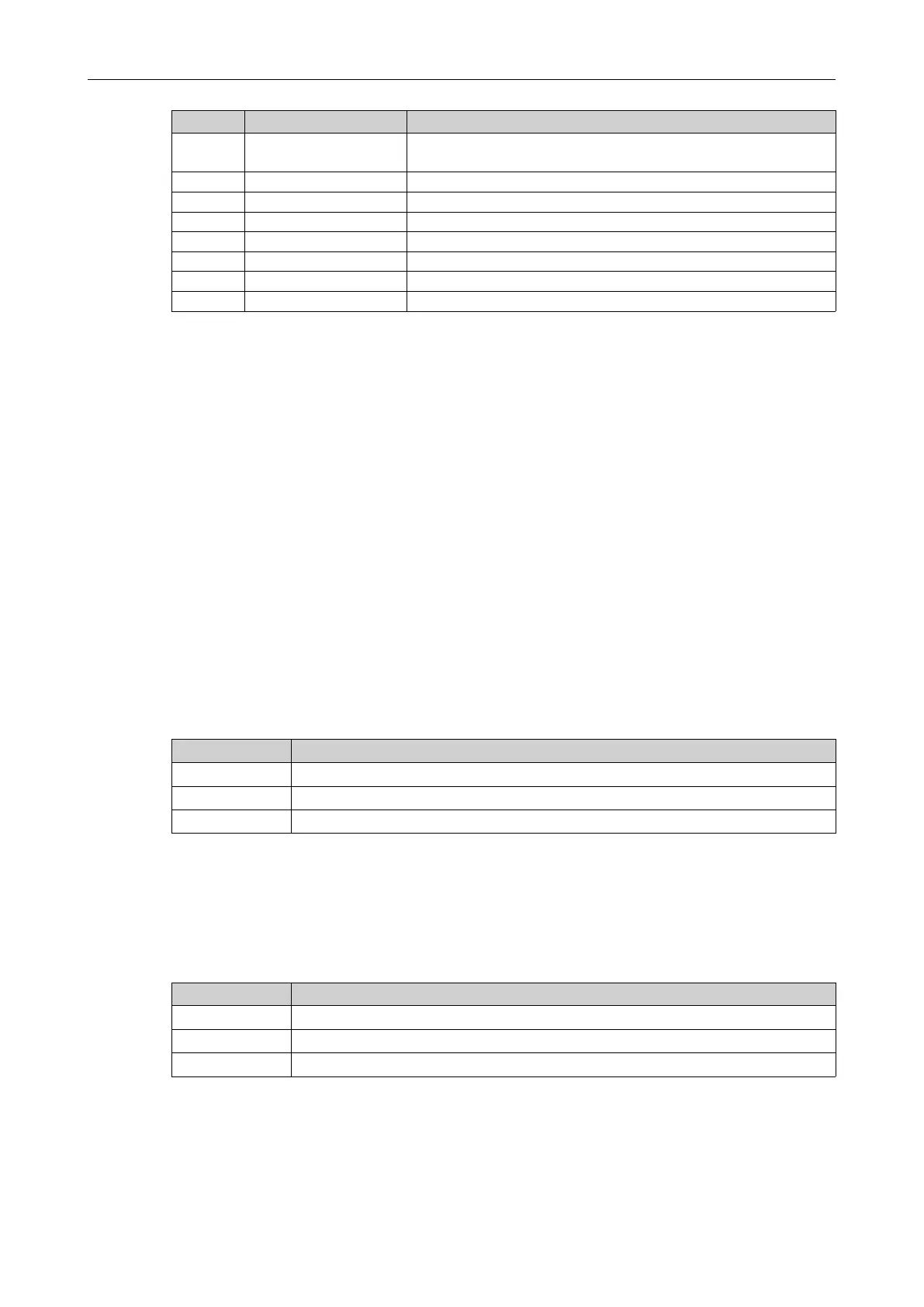
Setpoint
Function
Description
43
Reverse running
The terminal outputs an "active" signal when the AC drive runs in the
reverse direction.
44 Process 1
-
45 Process 2
-
46 Process 3
-
47 Process 4
-
48 Process 5
-
49 Process 6
-
50 Process 7
-
4.3.1 Virtual Digital Input (VDI)
VDI terminals have the same functions as DI terminals and can be used for multi-function digital
inputs.
VDI has three sources:
● A1-06. You can directly set A1-06 to make the DI active. It is mainly applicable to communication
scenarios, in which physical DIs are not used and DI functions are implemented by writing to A1-06.
The ones place of A1-06 corresponds to VDI1, the tens position of A1-06 corresponds to VDI2, and so
on.
● DO/RO state. The AC drive has five DO/RO terminals. DO/RO1 corresponds to VDI1, DO/RO2
corresponds to VDI2, and so on.
● DI state. DI1 corresponds to VDI1, DI2 corresponds to VDI2, and so on.
The following examples illustrate how to use the VDI.
Example 1: A1-05 (VDI1 active state source) is set to 00001 (DO/RO state). To enable the AC drive to
report a fault alarm and stop when the AI1 input exceeds the upper or lower limit, set as follows.
Step
Setting Parameters
1
Assign VDI1 with function "user-defined fault 1" (A1-00 = 12).
2
Assign DO/ RO1 with function "AI input limit exceeded" (F5-01 = 34).
3
Set the VDI1 active state source to DO state (A1-05 = 00001).
After the setting, when the AI1 input exceeds the upper or lower limit, the DO/RO1 terminal outputs an
ON signal. In this case, VDI1 becomes active and the AC drive receives user-defined fault 1 through
VDI1. Then the AC drive reports E27.00 and stops.
Example 2: To use the VDI to implement the emergency stop function without physical DIs in a
communication scenario, set as follows:
Step
Setting Parameters
1
Assign VDI1 with function "emergency stop" (A1-00 = 45).
2
Set the VDI1 active state source to the parameter (A1-05 = 00000).
3
Change the value of the ones place of A1-06 through communication.
After the setting, the emergency stop function can be implemented when the ones place of A1-06 is set
to 1 through communication.

 Loading...


