Function Applications
-480-
Para. No. Name
Default
Value Range Description
F3-16
Voltage fall time
of V/f separation
0.0s
0.0s to 1000.0s
Note: This parameter
indicates the time
required for the
voltage to change
from 0 V to the rated
motor voltage.
This parameter indicates the time required for the output voltage to fall from
the V/f separation voltage reference to 0. In V/f half separation mode, this
parameter is invalid, and the voltage fall time is the same as that set by F0-18.
F3-17
Stop mode for V/
f separation
0
0: The frequency and
voltage decrease to 0
independently
1: The frequency
decreases to 0 after
the voltage decreases
to 0
0: The frequency and voltage decrease to 0 independently
1: The frequency decreases to 0 after the voltage decreases to 0
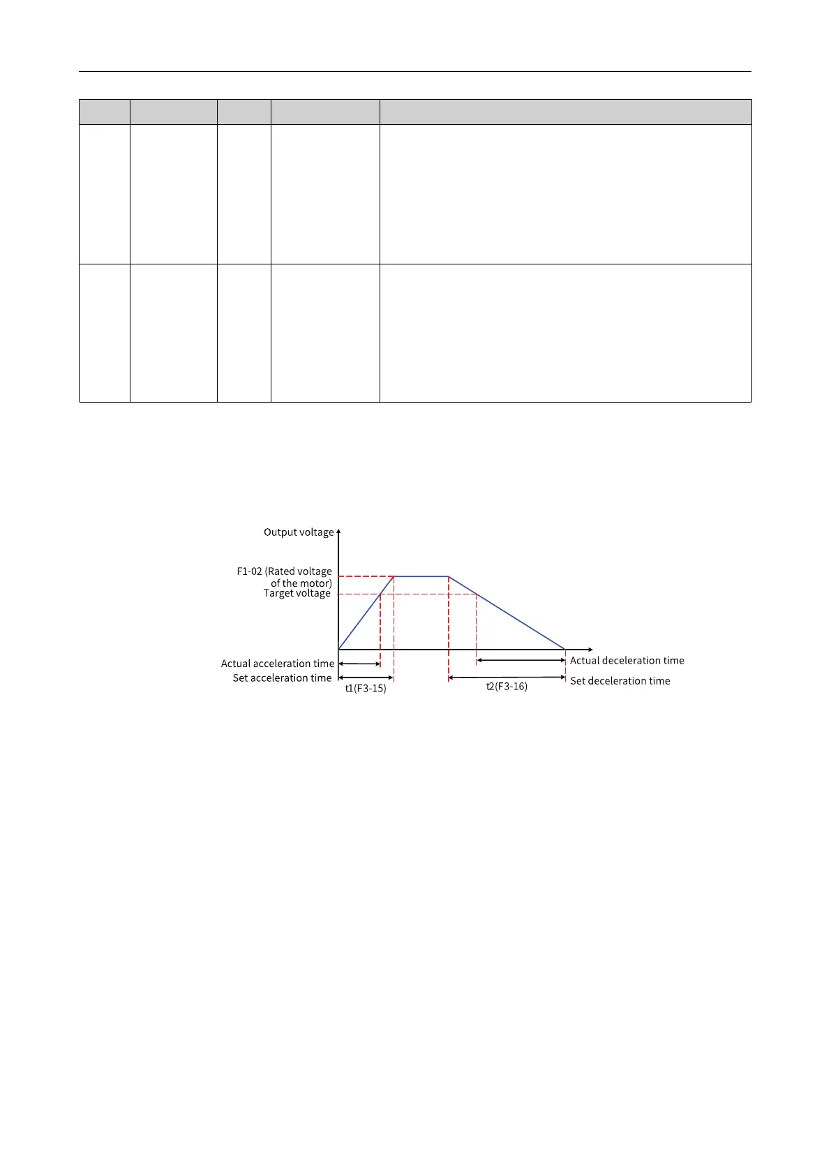
The voltage rise time of V/f separation indicates the time required for the voltage to rise from 0 to the
rated motor voltage. See t1 in the following figure.
The voltage fall time of V/f separation indicates the time required for the voltage to fall from rated
motor voltage to 0. See t2 in the following figure.
Figure 4-37 Schematic diagram of V/f separation
4.4.2 Output Current (Torque) Limit
During acceleration, operation at constant speed, or deceleration, if the current exceeds the
overcurrent stall action current (default: 150%, indicating 1.5 times the rated AC drive current), the
current limit mechanism is activated. In this case, the output frequency decreases until the current
drops below the overcurrent stall action current. Then, the output frequency increases toward the
target frequency. Therefore, the acceleration is prolonged. If the actual acceleration time cannot meet
your requirement, increase the value of overcurrent stall action current (F3-18) accordingly.

 Loading...


