Function Applications
-472-
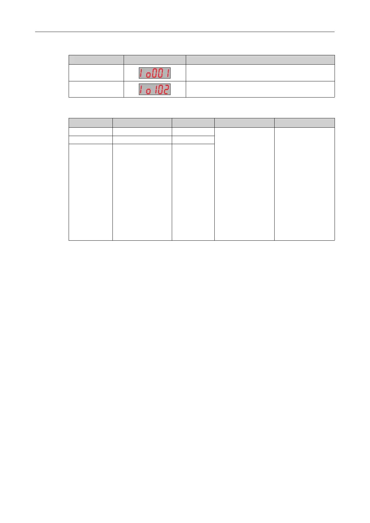
Example:
Para. No.
Display Description
F4-25
AI1 of the drive unit maps to analog or temperature input AI1
of the power supply unit.
F4-27
AI2 of the drive unit maps to analog or temperature input AI2
of extension card 1.
Table 4–22 Related parameters
Para. No. Name
Default
Value Range Description
F4-25
AI1 hardware source
0
0: None
1: AI1 of the power
supply unit
2: AI2 of the power
supply unit
101: AI1 of extension
card 1
102: AI2 of extension
card 1
201: AI1 of extension
card 2
202: AI2 of extension
card 2
This parameter defines
the analog/temperature
input source.
F4-27 AI2 hardware source
0
F4-29
AI3 hardware source
0
The value range of the parameters in the preceding table changes automatically. For details, see
“
4.3.1.1 Sources of DI Terminals
”
on page 458
.
4.3.4.2 Functions of Analog or Temperature Input Terminals
You can configure three analog inputs for the drive unit and map the analog data of the power supply
unit or extension cards by selecting the analog or temperature input sources. Analog data values and
analog functions (voltage, current, or temperature) are received through the internal bus.
You can set the filter time and analog input functions of the two analog inputs of the power supply
unit, and you can also set those of the external extension cards.

 Loading...


