286
Intel
®
855GME Chipset and Intel
®
6300ESB ICH Embedded Platform Design Guide
Schematic Checklist Summary
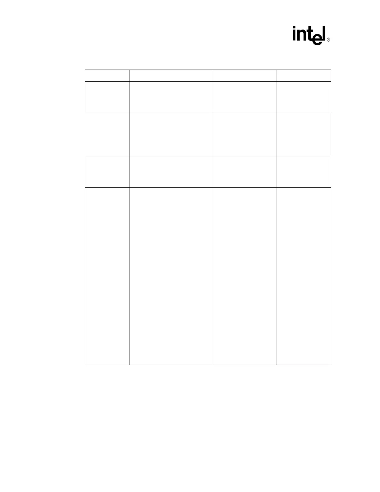
PERR#, PLOCK#
Recommend an 8.2 K
Ω pull-up
resistor to V
CC
3.3 or a 2.7 Ω K pull-
up resistor to V
CC
5.
Recommend an 8.2 K
Ω
pull-up resistor to V
CC
3.3
or a 2.7 K
Ω pull-up resistor
to V
CC
5.
See
PCI 2.2
Component
Specification
pull-up
recommendations for
V
CC
3.3 and V
CC
5.
PME# No extra pull-up needed. May leave as no connect.
PME# is in the
Resume power plane
and has an internal
pull-up resistor. See
sectionSection 9.10.4
for PME# wiring
recommendations.
SERR#, STOP#,
TRDY#
Recommend an 8.2 K
Ω pull-up
resistor to V
CC
3.3 or a 2.7 KΩ pull-
up resistor to V
CC
5.
Recommend an 8.2 K
Ω
pull-up resistor to V
CC
3.3
or a 2.7 K
Ω pull-up resistor
to V
CC
5.
See
PCI 2.2
Component
Specification
pull-up
recommendations for
V
CC
3.3 and V
CC
5.
PIRQ[H:E]#/
GPIO[5:2]
Recommend a 2.7 K
Ω pull-up
resistor to V
CC
5 or 8.2 KΩ resistor
to V
CC
3.3.
Recommend a 2.7 K
Ω
pull-up resistor to V
CC
5 or
8.2 K
Ω resistor to V
CC
3.3.
In Non-APIC Mode,
the PIRQx# signals
may be routed to
interrupts 3, 4, 5, 6, 7,
9, 10, 11, 12, 14 or 15
as described in
Section 9.9.2.
Each PIRQx# line has
a separate Route
Control Register. (See
the 6300ESB EDS for
more information.)
In APIC mode, these
signals are connected
to the internal I/O
APIC in the following
fashion:
•PIRQ[E]# is
connected to
IRQ20
•PIRQ[F]# is
connected to
IRQ21
• PIRQ[G]# is
connected to
IRQ22
•PIRQ[H]# is
connected to
IRQ23
Table 133. PCI Interface Checklist (Sheet 2 of 3)
Checklist Items Recommendations Interface not used Reason/Impact