Chapter 1 Application scenario 7
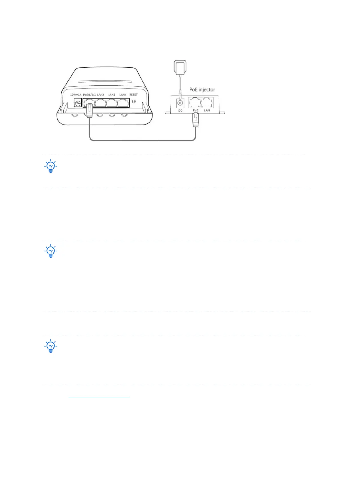
(3) Connect the PoE injectors to power sockets. The Power LED indicators of the CPEs light
up.
Refer to your actual product for the supported PoE power supply distance.
----End
After the two CPEs are powered on, they will bridge to each other automatically. When the
LED1, LED2 and LED3 indicators of a CPE light solid on while the LED1, LED2 and LED3
indicators of the other CPE blink, the peer-to-peer bridging succeeds.
− After the bridging succeeds, the DHCP servers of the two CPEs are disabled. The IP address of the CPE
working in AP mode remains the same (192.168.2.1), while the IP address of the CPE working in Client
mode changes to 192.168.2.2.
− If the peer-to-peer automatic bridging fails, reset the two CPEs to factory settings, and try again. Reset
method: With the CPE powered on, hold down the reset button for about 8 seconds, and then release it
when all indicators light up and then turn off. The CPE is restored to factory settings successfully.
Scenario 2: Peer-to-multiple peers bridging
− For peer-to-multiple peers bridging, perform peer-to-peer bridging first, and then power on the rest
CPEs within 30 minutes.
− A CPE can bridge to 15 CPEs at most.
1. Refer to Peer-to-peer bridging to make any two CPEs bridge to each other.
2. Within 30 minutes after the peer-to-peer bridging succeeds, place the rest CPEs which are in
factory settings near the CPE with the LED1, LED2, and LED3 indicators solid on and power
them on.
----End