Chapter 6 Network 96
6.5.2 Example of configuring VLAN
Network requirement
You use CPEs to set up CCTV surveillance networks. CPE1 and CPE2 are used to connect to IP
cameras in different places and cannot communicate with each other.
You can assign CPE1 and CPE2 to different VLANs.
Assume that:
− CPE1 is assigned to VLAN10, and CPE2 is assigned to VLAN20.
− The router in the network supports IEEE 802.1q VLAN and enables two DHCP servers
which belong to VLAN10 and VLAN 20 respectively.
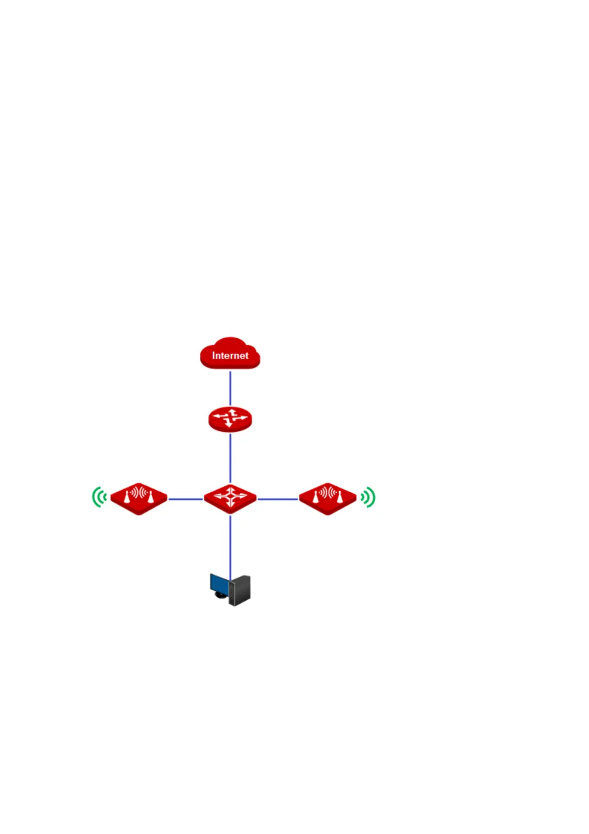
Network topology
The connections of the switch:
− The router is connected to the uplink port
− CPE1 is connected to port 1
− CPE2 is connected to port 2