Chapter 1 Application scenario 9
Option 2 Manual bridging
1. Place the two CPEs next to each other.
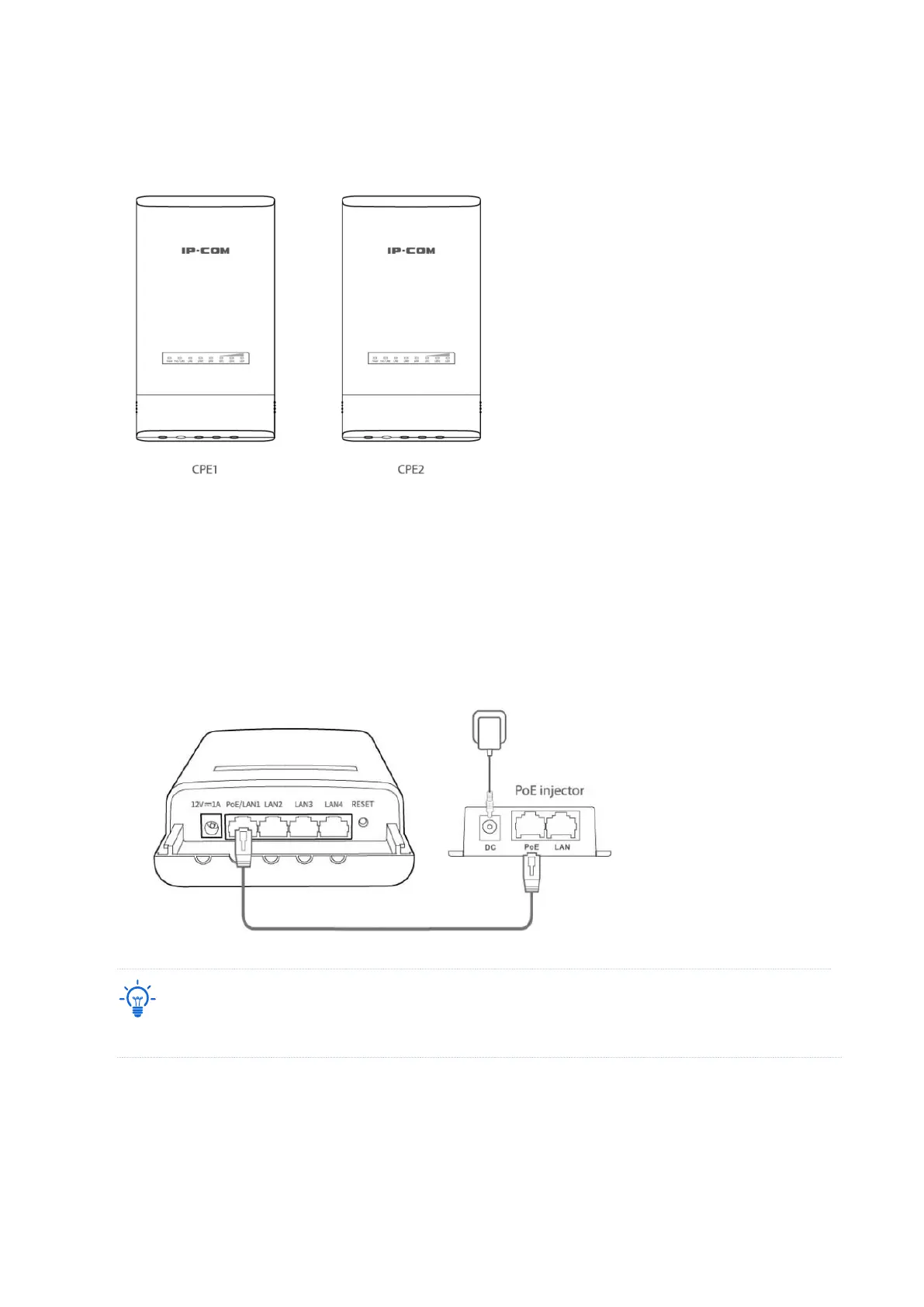
2. Power on the CPE1 (powered by PoE in this example).
(1) Uncover the housing of CPE1.
(2) Use an Ethernet cable (CAT5e or better is recommended) to connect the PoE/LAN port of
CPE1 to the PoE port of the included PoE injector to power it on.
(3) Use the included power adaptor to connect the PoE injector to a power socket. The
Power LED indicator of the CPE1 lights up.
Refer to your actual product for the supported PoE power supply distance.
PoE