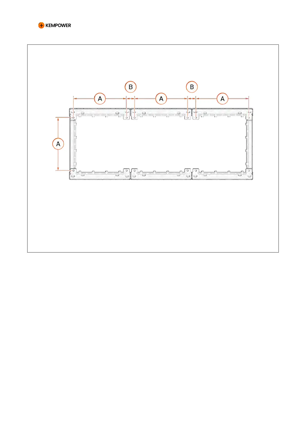
Figure 61. Triple cabinet footprint and fixing points (mm)
A 520
B 80
10. EXAMPLES OF CONNECTING OUTPUT AND CONTROL CABLES
TO CHARGING POINTS
In the cabinet, the DC output (OUT n) and control cable (CT n) terminals are
numbered.
In the double Satellite, the DC input terminals are marked CAB 1 (right-hand
side) and CAB 2 (left-hand side), and the control cable terminals CT A
(right-hand side) and CT B (left-hand side). In the single Satellite, the
vehicle connector is always on the right-hand side.
Connect the corresponding output and control cable pairs from
the cabinet to the same Satellite. If the site has several Satellites,
connect them in ascending order starting from cabinet terminal 1 to Satellite
1. If the cabinet has more DC output terminals than you need, leave the last
terminals empty.
CHARGING EQUIPMENT FOR ELECTRIC VEHICLES INSTALLATION MANUAL
CONFIDENTIAL – CERTIFIED PARTNERS 132 REV 2.40 EN 04-2024