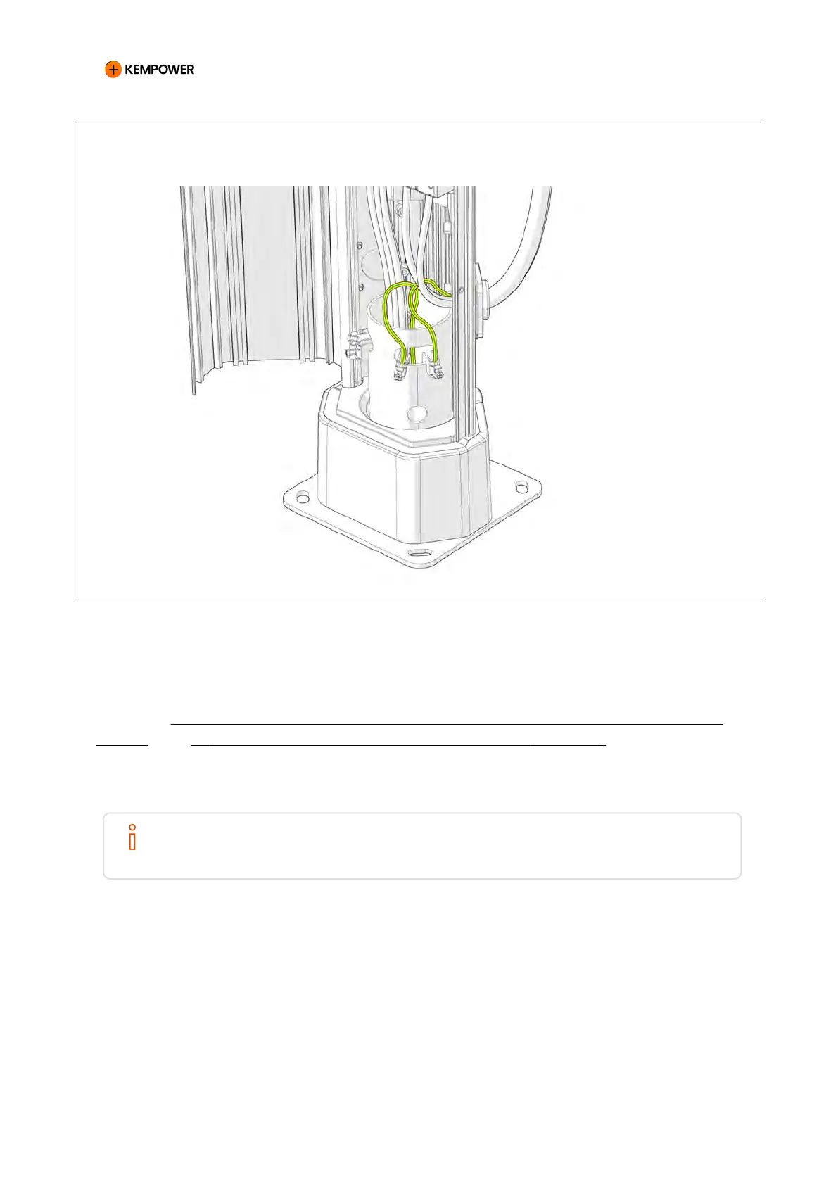
Figure 46. Connecting the PE wires to the installation flange using PE clamps
The terminals are numbered and labeled. Start from terminal 1 in the cabinet
and continue in ascending order. If there are more terminals than cables,
leave the last ones empty.
See also 10: Examples of connecting output and control cables to charging
points and 11: Examples of connecting cables to the Satellites.
5.2.10. Installing the control cables
NOTE
Label the cables clearly at both ends. Documenting which output supplies which
charging point helps with later troubleshooting.
The control cable between the charging power unit and the charging point
consists of the following:
• Signal line (CT)
• Single Satellite (one vehicle connector): terminal block CT A (CT
A and CT B are jumpered together)
• Double Satellite Version 2 (two vehicle connectors): terminal blocks
CT A and CT B
CHARGING EQUIPMENT FOR ELECTRIC VEHICLES INSTALLATION MANUAL
CONFIDENTIAL – CERTIFIED PARTNERS 94 REV 2.40 EN 04-2024