Depending on the needed charging capacity, you can connect DC outputs
in parallel in the cabinet to form one configuration output. Connect the
corresponding configuration output and control cable pair to the same
Satellite.
The ChargEye connector is configured in ChargEye during commissioning.
The first number notates the sequence number of the Satellite, and the
second number notates the vehicle connector. Number 2 is the right-hand
side vehicle connector, and number 1 the left-hand side vehicle connector.
The CHAdeMO vehicle connector is the exception and it is always number 2
regardless of which side it is on.
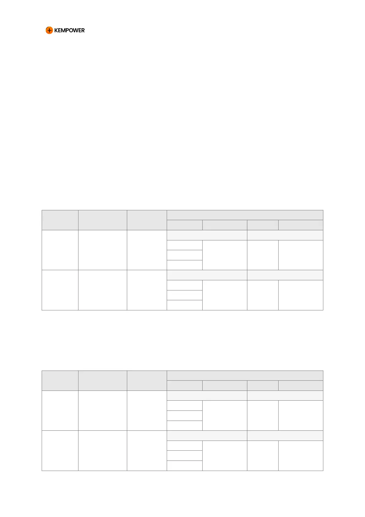
10.1. Dynamic (Ds2) – 1 double Satellite
Table 5. Ds2 connected to 1 double Satellites (2 x 375 A configuration output)
Config.
output
ChargEye
connector
Max. cur-
rent
Terminals
DC output Control cable DC input Control cable
1 12 (right) 375 A Power Unit 1 Satellite 1
OUT 1 CT 1 CAB 1 CT A
OUT 5
OUT 3
2 11 (left) 375 A Power Unit 1 Satellite 1
OUT 2 CT 2 CAB 2 CT B
OUT 6
OUT 4
10.2. Dynamic (Ds2) – 2 single Satellites
Table 6. Ds2 connected to 2 single Satellites (2 x 500 A configuration output)
Config.
output
ChargEye
connector
Max. cur-
rent
Terminals
DC output Control cable DC input Control cable
1 12 (right) 500 A Power Unit 1 Satellite 1
OUT 1 CT 1 CAB 1 CT A
OUT 5
OUT 3
2 22 (right) 500 A Power Unit 1 Satellite 2
OUT 2 CT 2 CAB 1 CT A
OUT 6
OUT 4
CHARGING EQUIPMENT FOR ELECTRIC VEHICLES INSTALLATION MANUAL
CONFIDENTIAL – CERTIFIED PARTNERS 133 REV 2.40 EN 04-2024