11.10. Control Unit 200 A with one CCS vehicle connector
NOTE
Grounding of the Ethernet shield at one end only, charging power unit or Control Unit.
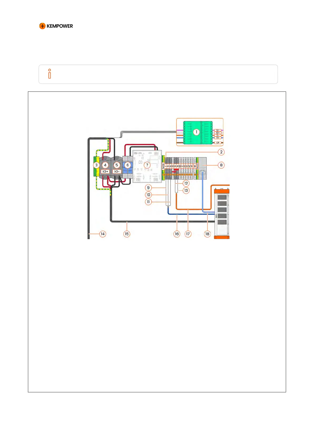
Figure 71. Control Unit 200 A with one combined charging system (CCS) vehicle connector
1 Terminal block for power cable PE 10 Control cable ground wire
2 Fuse terminal block (24 VDC, 2 A) 11 Control cable (CT A)
3 Charging cable Phoenix
Connector
12 Equipment stop button
4 DC+ terminal (X2+) 13 Equipment stop button
communication cable
5 DC- terminal (X2-) 14 DC power charging cable (vehicle
connector)
6 DC Voltage measurement fuses
(1000 VDC)
15 DC power cable from cabinet
7 Voltage and insulation monitor
(A019)
16 Control cable
8 Ethernet terminal 17 Equipment stop button cable
9 Control cable auxiliary power
wires (+24 V)
18 Communication cable
CHARGING EQUIPMENT FOR ELECTRIC VEHICLES INSTALLATION MANUAL
CONFIDENTIAL – CERTIFIED PARTNERS 148 REV 2.40 EN 04-2024