11.5. Satellite Version 2 with two CCS vehicle connectors
NOTE
Grounding of the Ethernet shield at one end only, charging power unit or Satellite.
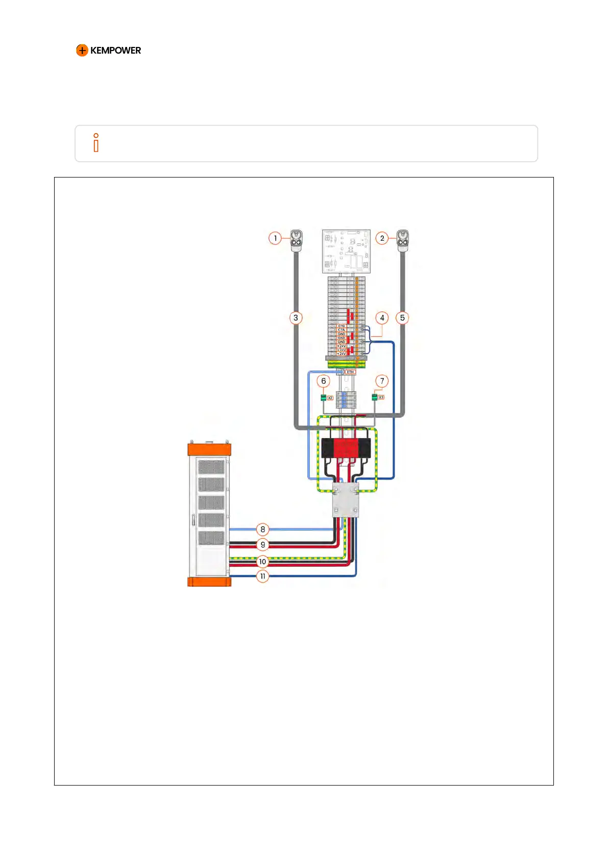
Figure 66. Satellite Version 2 with two combined charging system (CCS) vehicle connectors
1 Configuration tag (left vehicle
connector)
7 Vehicle connector signal wire
(right)
2 Configuration tag (right vehicle
connector)
8 Communication cable
3 Charging cable (left) 9 DC output power cables (left)
4 CT line signal wires 10 DC output power cables + PE
(right)
5 Charging cable (right) 11 Control cable (CT line)
6 Vehicle connector signal wire (left)
CHARGING EQUIPMENT FOR ELECTRIC VEHICLES INSTALLATION MANUAL
CONFIDENTIAL – CERTIFIED PARTNERS 143 REV 2.40 EN 04-2024