3.4.3. Control module
The control module handles the communication in the charging power unit.
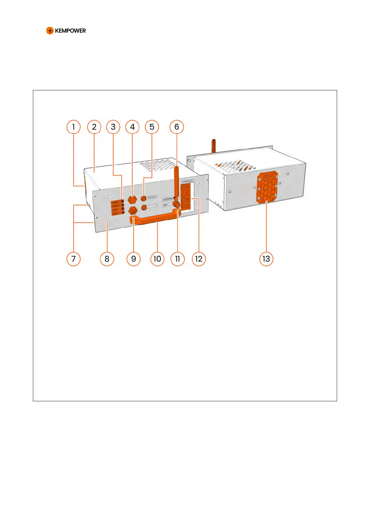
Figure 8. Control module overview
1 Mounting plate for printed circuit
boards
8 Front panel
2 Cover 9 Ethernet port (external)
3 Antenna cable connectors 10 Handle
4 USB port 11 SIM card adapter (for customer
SIM)
5 Status indicator
a
12 Ethernet switch (internal)
6 Antenna (for customer modem) 13 Multi-quick connector
7 Rollers
a
Green: OK, ready for operation. Blue: operation. Red: error.
CHARGING EQUIPMENT FOR ELECTRIC VEHICLES INSTALLATION MANUAL
CONFIDENTIAL – CERTIFIED PARTNERS 19 REV 2.40 EN 04-2024