11.11. AC Satellite Version 2 with two vehicle connectors
NOTICE
The AC Satellite is not connected to the charging power unit. It requires only AC
supply cables that are connected to the main AC supply.
NOTE
If the optional communication cable is used, ground the Ethernet shield at one end
only: AC Satellite or network connection switch.
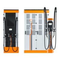
Figure 72. AC Satellite Version 2 with two vehicle connectors
1 Configuration tag (left vehicle
connector)
8 Contactor (right)
2 Configuration tag (right vehicle
connector)
9 kWh meter (left)
3 Connection for equipment stop
(option)
10 kWh meter (right)
4 Socket signal wires (left) 11 Operating power circuit breaker
5 Socket signal wires (right) 12 Ethernet (public LAN)
communication cable (option)
6 Residual current monitoring
sensors
13 AC input 2
a
7 Contactor (left) 14 AC input 1
a
If the site has multiple AC Satellites, we recommend shifting the phase order L1→L2.2 | L2→L3.2 |
L3→1.2 to balance the power consumption in the grid.
CHARGING EQUIPMENT FOR ELECTRIC VEHICLES INSTALLATION MANUAL
CONFIDENTIAL – CERTIFIED PARTNERS 149 REV 2.40 EN 04-2024