DIAGNOSTICS Checkout Procedures
10DEC05
DG4825-1
Page
146 of 180
2 If the measurements are not correct, do the checkout for the POWER SUPPLY PS1.
Important
To do Step 3, you must:
• install the INTERLOCK KEY, or
• close the FRONT DOOR
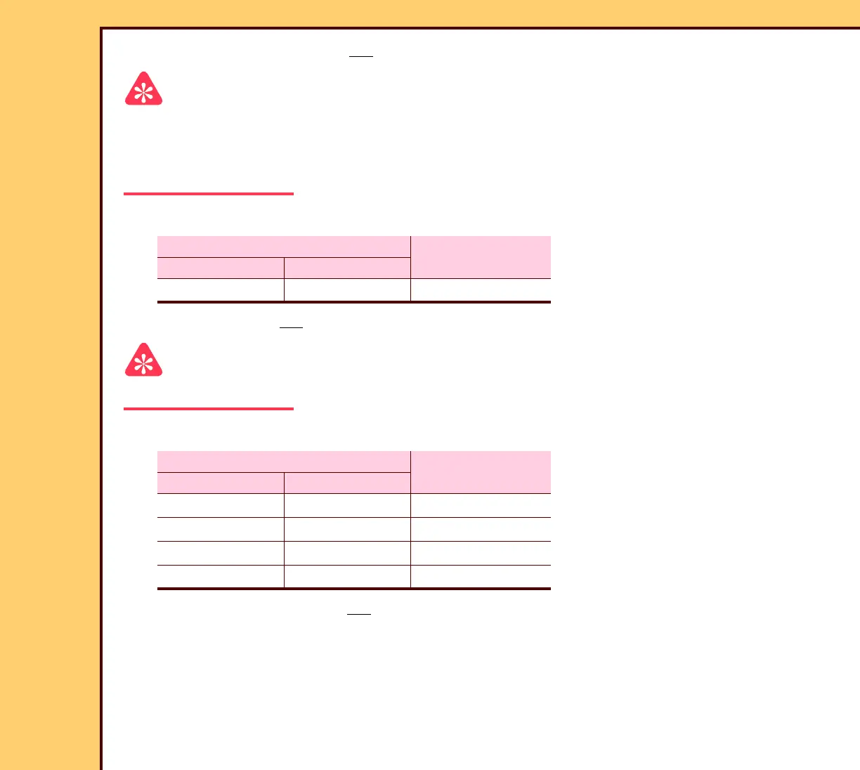
3 Check the voltages at the test points:
4 If the voltage is not correct, do the checkout for the INTERLOCK SWITCH S8.
Important
To check the +10 V DC, do the adjustment for the GALVO BOARD A4.
5 Check the voltages at the test points:
6 If any of the voltages do not match the table, install a new GALVO BOARD A4.
MULTIMETER
Voltage
Ground Positive
TP1 TP16 –24 ± 0.5 V DC
MULTIMETER
Voltage
Negative Positive
TP1 TP5 +15 ± 0.25 V DC
TP1 TP6 −15 ± 0.25 V DC
TP1 TP13 +10 ± 0.1 V DC
TP1 TP15 +5 ± 0.1 V DC
 Loading...


