DIAGNOSTICS Checkout Procedures
10DEC05
DG4825-1
Page
151 of 180
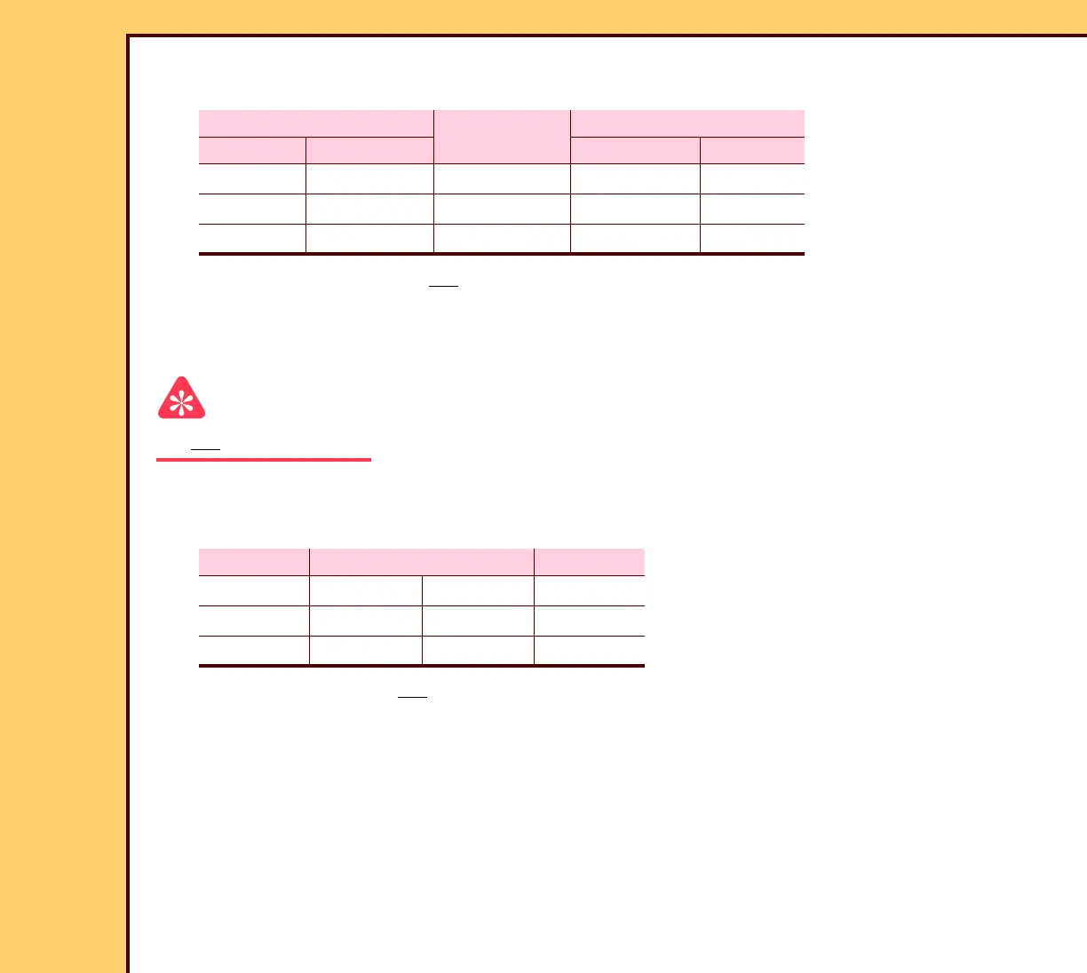
12 Manually rotate the SLOW SCAN AY and check for the correct voltage measurements at
the following test points:
13 If a measurement does not match the specification, install a new COIL BOARD A7.
14 Connect the CONNECTOR J1.
15 Check the COILS and FUSES on the COIL BOARD A7.
Important
Do not rotate the SLOW SCAN AY when you measure the following resistances.
16 Disconnect the CABLE from the CONNECTOR J4.
17 Without moving the SLOW SCAN AY, measure the resistance:
18 If a measurement is not correct, install a new COIL BOARD A7. Use COIL BOARD A7,
ENCODER and SLOW SCAN ROTOR.
19 Connect the CONNECTOR J4.
MULTIMETER
HALL EFFECT
SENSOR
Voltage
Negative Positive High Low
TP17 TP14 HALL A 4 - 5 V DC < 1 V DC
TP17 TP16 HALL B 4 - 5 V DC < 1 V DC
TP17 TP15 HALL C 4 - 5 V DC < 1 V DC
Phase PINS on CABLE P4 Ω
A P4-8 P4-12 5 - 8
B P4-2 P4-16 5 - 8
C P4-6 P4-18 5 - 8
 Loading...


