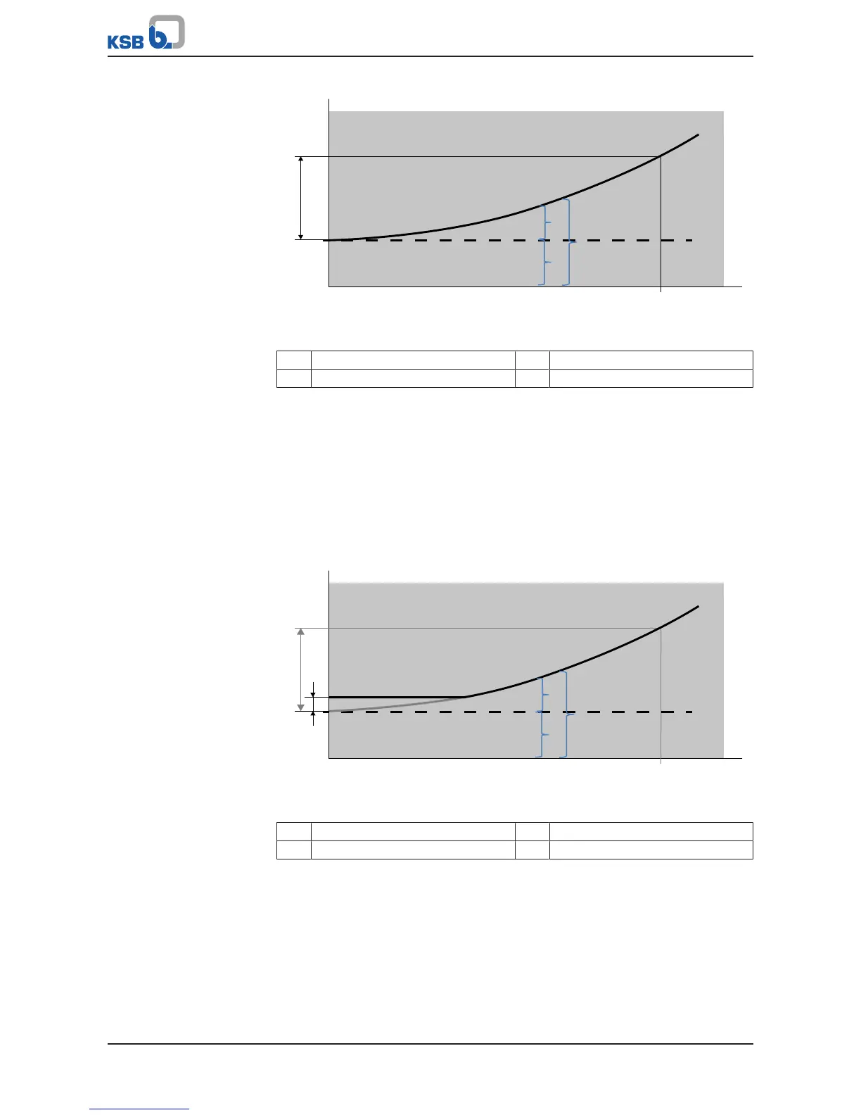
Fig.69: Setpoint compensation curve for dynamic pressure compensation based on
flow rate
1 Flow rate independent setpoint 2 Setpoint compensation
3 Compensated setpoint
The compensated setpoint (3) is the sum of the flow rate independent setpoint (1)
and setpoint compensation (2). The flow rate independent setpoint (1) is configured
as described in (ðSection8.6,Page70) . Setpoint compensation (2) starts at flow
rate Q = 0 and reaches the value defined under Setpoint Compensation (3-9-3-4) at
the Dyn Press Comp Q Data Point (3-9-3-2) flow rate. Beyond that, setpoint
compensation continues along the parabola shown.
The relatively small pressures in the lower flow rate range may not be sufficient to
open installed swing check valves. In order to achieve the pressure required in this
range, parameter (3-9-3-5) can be used to define a minimum setpoint compensation
value. The following diagram shows the influence of minimum setpoint
compensation on the setpoint compensation curve.
Fig.70: Setpoint compensation curve for dynamic pressure compensation based on
flow rate with minimum setpoint compensation (3-9-3-5)
1 Flow rate independent setpoint 2 Setpoint compensation
3 Compensated setpoint
Based on speed (for closed hydraulic circuits)
If neither the measured nor estimated flow rate is available, dynamic pressure
compensation can be realised based on speed. This is only possible for closed
hydraulic circuits and single-pump configurations, however. To this end, the Dynamic
Pressure Compensation Method parameter (3-9-3-1) is set to Speed.
The following diagram shows the setpoint compensation curve (solid line) as a
function of the speed and relevant parameters.