8 Commissioning/Shutdown
79 of 212
PumpDrive 2
Parameter Description Possible settings Factory setting
3-8-2-2 Analog Input 2 Function
Function of analog input2. Internal
operating values cannot be used as an
actual value source.
Differential Pressure OFF
3-8-2-3 Analog Input 2 Lower Limit 0,00 0,00
3-8-2-4 Analog Input 2 Upper Limit 10,00 100,00
1-3-1 System Start / Stop
This function is used to start the system.
Start Stop
NOTE
The System Start/ Stop parameter (1-3-1) must be set to Stop if the system start
takes place via the digital input.
8.7.1.2.2 Closed-loop control mode with external setpoint signal
The setpoint can be specified via an external setpoint signal. If a setpoint is
simultaneously specified via the control panel, the setpoint via the analog input has a
higher priority (ðSection8.2,Page65) .
NOTE
The parameter values and value ranges/units entered are mutually dependent. This
is why the first step in parameterising the frequency inverter is always to specify the
applicable value range and units (refer to parameter 3-11). If the value range or
unit is subsequently changed, all dependent parameters must be checked for
correctness again.
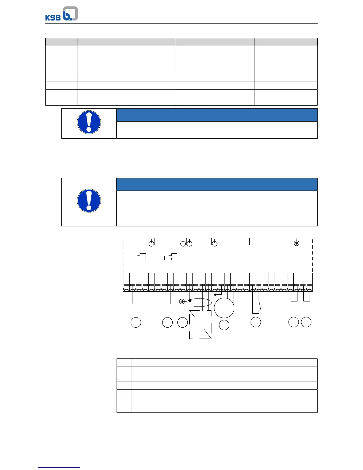
Fig.60: Terminal wiring diagram, closed-loop control mode (dashed line = optional)
1 Start / Stop 2
2 Feedback value transmitter
3 Signal relay 1 (ðSection8.10.3,Page120)
4 Signal relay 2 (ðSection8.10.3,Page120)
5 Digital enable input
6 Ground for digital inputs
7 External setpoint signal
Example
The frequency inverter is to control the system to achieve a setpoint of 6.7bar in a
differential pressure control process. For this purpose, a differential pressure sensor
(4 - 20mA) with a measuring range of 0 to 10bar is connected to analog input 2 of