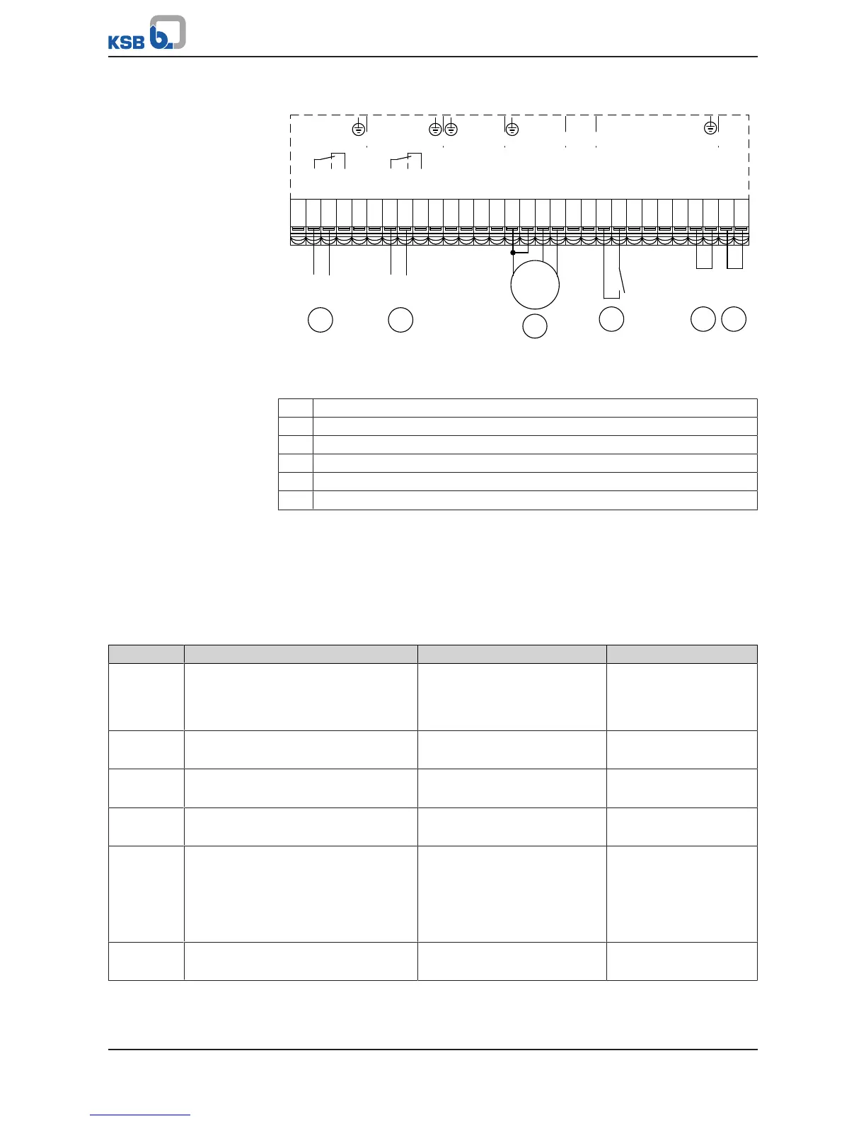
Fig.59: Terminal wiring diagram, closed-loop control mode (dashed line = optional)
1 Start / Stop 2
2 Feedback value transmitter
3 Signal relay 1 (ðSection8.10.3,Page120)
4 Signal relay 2 (ðSection8.10.3,Page120)
5 Digital enable input
6 Ground for digital inputs
Example
The frequency inverter is to control the system to achieve a setpoint of 6.7bar in a
differential pressure control process. For this purpose, a differential pressure sensor
(4 - 20mA) with a measuring range of 0 to 10bar is connected to analog input 2 of
the frequency inverter. The setpoint is specified using the control panel. The system
start is activated by the System Start / Stop (1-3-1) parameter. The frequency inverter
starts as soon as it is set to automatic or manual mode and the enable is given via DI-
EN.
Table53: Example of closed-loop control mode with setpoint specification via the control panel
Parameter Description Possible settings Factory setting
3-6-1 Type of Control
Selecting the control method. The
controller is deactivated when OFF (Open-
loop Control) is selected.
Differential Pressure Dependent on pump
3-11-2-1 Minimum Pressure
Minimum limit of measuring range
0,00 -1,00 bar
3-11-2-2 Maximum Pressure
Maximum limit of measuring range
10,0 1000,0 bar
3-11-2-3 Pressure Unit
Configurable unit for pressure 1
bar bar
1-3-2 Setpoint (Closed-loop Control)
Configurable setpoint. This parameter is
disabled if the setpoint is specified via
DIGIN/ANIN. Otherwise, the setpoint
source is selected via the Control Point
parameter (Local/Field Bus).
6,7 bar 0,00 bar
3-8-2-1 Analog Input 2 Signal
Sensor signal at analog input 2
4…20mA OFF