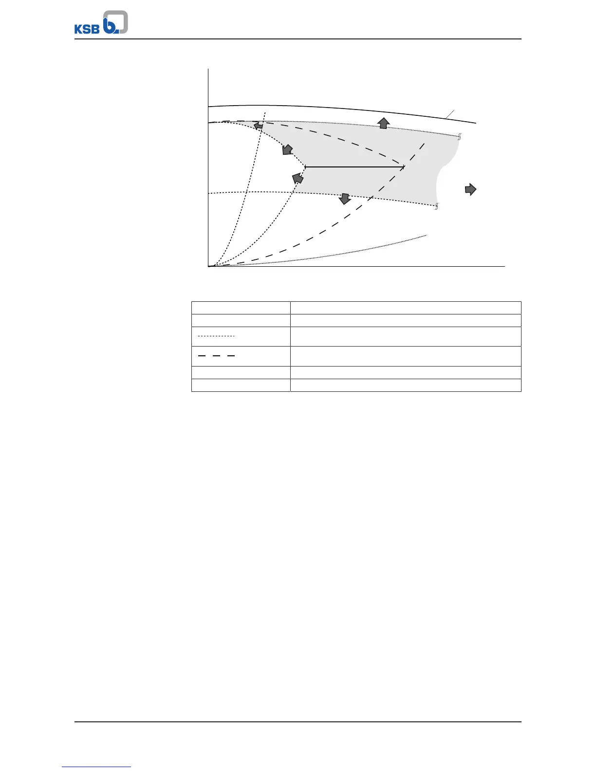
Fig.62: Switching limits of two running pumps in a multiple pump system
1 Characteristic head curve of a running pump
2 Characteristic head curve of two running pumps
Stop limits: Stopping the second pump
Start limits: Starting the third pump
Arrows Effective direction of the switching limits
Coloured area Operating range of two running pumps
KSB PumpDynamicControl (3-7-3-6):
This parameter determines the position of the stop limits relative to the start limits;
see "Switching limits of two running pumps in a multiple pump system" diagram and
greatly impacts the dynamic response and energy efficiency of the system. The
parameter can be defined anywhere from 0% for maximum energy efficiency to
100% for maximum dynamic response.
Low values mean that only the number of pumps required from a practical energy
perspective operate, or run. Fast, extensive changes in demand may possibly be
responded to with a delay as switching operations occur relatively frequently. Values
which are set too low, however, can lead to unstable starting and stopping cycles.
High values enable quick response to fast, extensive changes in demand as a
relatively large number of pumps run and switching operations do not occur as
frequently. High values can also lead to high energy consumption, however. The
following procedure is recommended for setting this parameter: Starting with a low
value (e.g. 10%), the parameter is gradually increased until the response time of the
multiple pump system suits the application. If this is already the case with the initial
value set, decreasing the value may prove even more beneficial.
Minimum Time Between Starts (3-7-3-1):
This parameter defines the minimum period of time that must lapse before a
subsequent start is carried out. Setting this parameter can prevent a second pump
from being started while a pump that was started just before is still running up to its
target speed along the start ramp. The minimum period of time between two starts
(3-7-3-1) should therefore be coordinated with the start ramp time (3-3-5-1). An
appropriate setting is achieved by selecting roughly the same times.
Minimum Time Between Stops (3-7-3-2):
This parameter defines the minimum period of time that must lapse before a
subsequent stop is carried out. Setting this parameter can prevent a second pump
from being stopped while a pump that was stopped just before is still running down