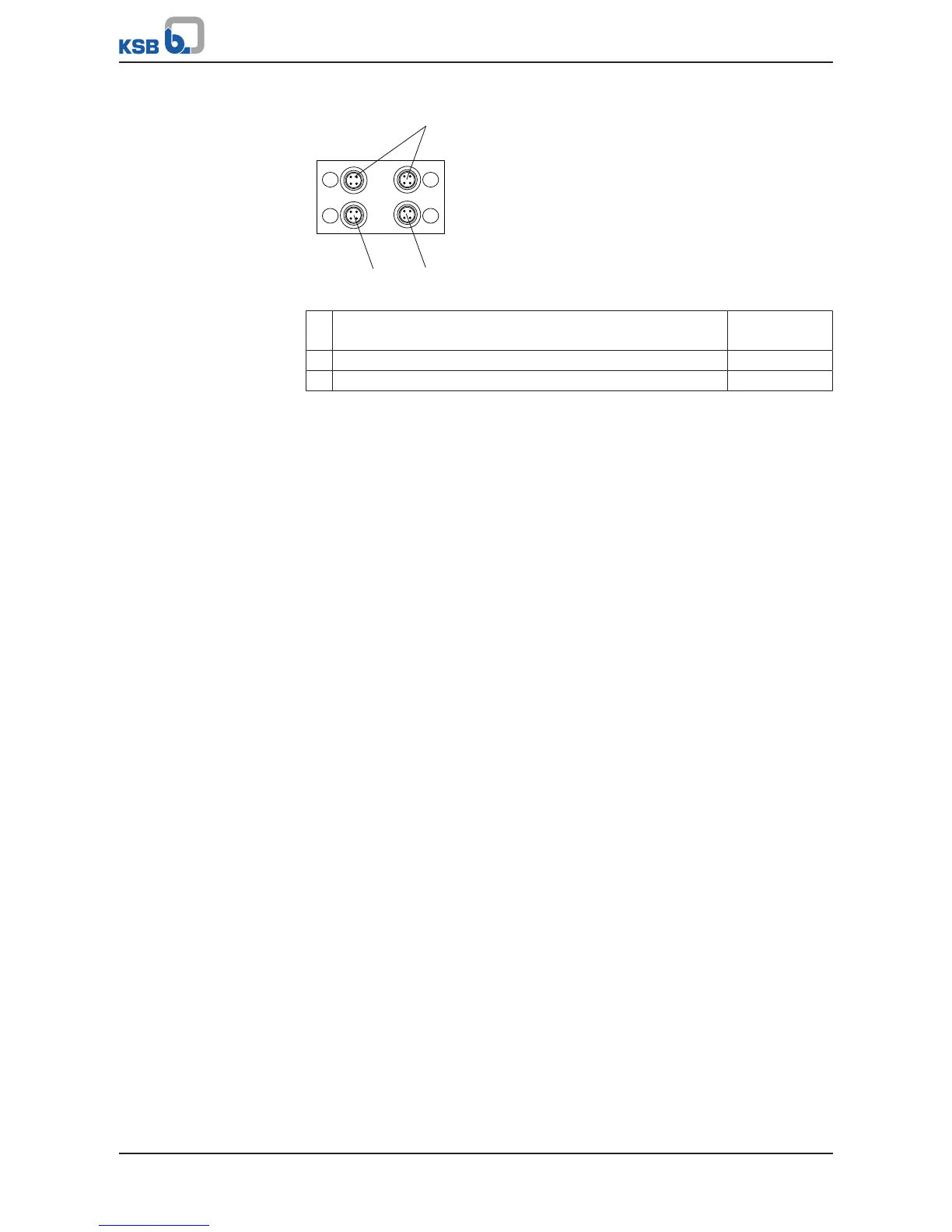
Fig.38: M12 module
1
Connection for dual/multiple pump configurations (KSB device
bus)
C - D
2 Connection for PumpMeter (Modbus) A
3 Connector for the bus cable crosslink (Modbus) B
▪ Can be retrofitted
▪ Internal T-connector (bus looped through) [uninterruptible even in the event of a
frequency inverter power failure]
▪ Pre-configured cables (ðSection12.2,Page197)
▪ Connector for self assembly (ðSection12.2,Page197)
The M12 slot module can be fitted in an available slot of the frequency inverter.