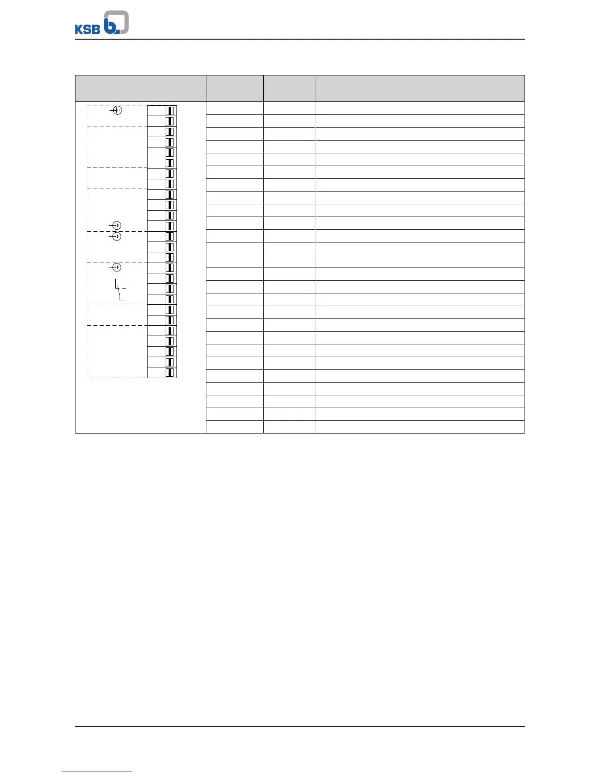
F8 GND Ground
F7 DICOM2 Ground for digital inputs
F6 DI8 Digital input 8
F5 DI7 Digital input 7
F4 DI6 Digital input 6
F3 +24V +24 V DC voltage source
F2 AO2-GND Ground for AN-OUT
F1 AO2 Analog current/voltage output
E10 +24V +24 V DC voltage source
E9 AIN3+ Differential analog input HI
E8 AIN3- Differential analog input LO
E7 GND Ground
E6 GND Ground
E5 DO2 Digital output 2
E4 DO1 Digital output 1
E3 GND Ground
E2 NC3 Relay, NC contact, "NC" No. 3
E1 NO3 Relay, NO contact, "NO" No. 3
D8 COM3 Relay, reference "COM" No. 3
D7 +24V +24 V DC voltage source
D6 NO8 Relay, NO contact, "NO" No. 8
D5 NO7 Relay, NO contact, "NO" No. 7
D4 NO6 Relay, NO contact, "NO" No. 6
D3 NO5 Relay, NO contact, "NO" No. 5
D2 NO4 Relay, NO contact, "NO" No. 4
D1 COM4-8 Relay, reference "COM" No. 4-8
Digital Inputs
▪ Three (3) digital inputs are available on the I/O extension board.
▪ The functions of digital inputs DI6 to DI8 can be parameterised as required.
The digital inputs are electrically isolated. The DICOM1 reference ground for the
digital inputs is thus also electrically isolated. If the internal 24V source is used, the
internal GND must also be connected to the electrically isolated DICOM2 ground of
the digital inputs. A wire jumper can be used between GND and DICOM2 for this
purpose.