8 Commissioning/Shutdown
114 of 212
PumpDrive 2
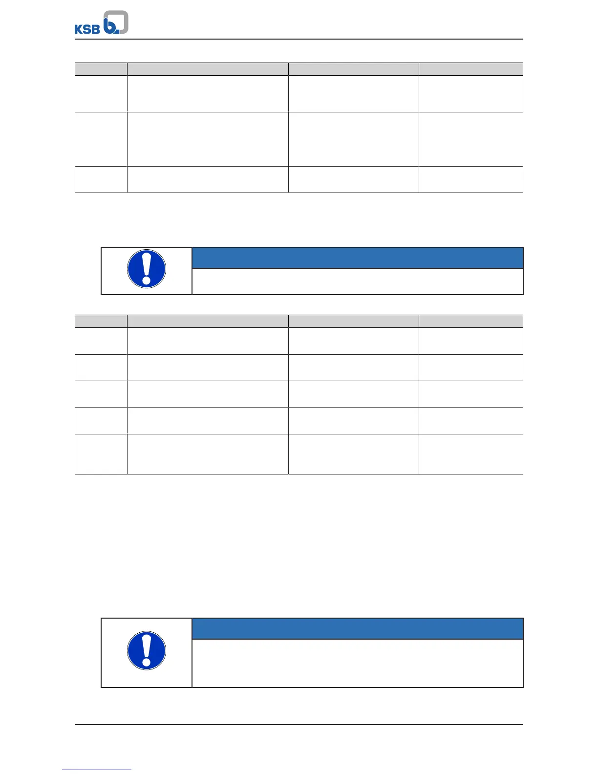
Parameter Description Possible settings Factory setting
3-13-2 Address
Modbus address of PumpMeter device
connected
1...247 247
3-13-3 Baud Rate
Modbus baud rate of PumpMeter device
connected
▪ 9600
▪ 19200
▪ 38400
▪ 115200
38400
3-13-4 System Bus Monitoring Period
Modbus time-out setting
1...180s 15
8.9.3 Date and time
The frequency inverter is equipped with a real-time clock. The output format can be
selected.
NOTE
Automatic toggling between summer and winter time is not possible.
Table84: Parameters for setting the date and time
Parameter Description Possible settings Factory setting
1-5-1 System Time
Current time of system
- -
1-5-2 System Date
Current date of system
- -
3-1-4-1 Set Date
Setting the date
01.01.2000 ... 31.12.2099 -
3-1-4-2 Set Time
Setting the time
00:00…23:59 -
3-1-4-3 Time Format
Selecting the format for displaying the time
▪ AM
▪ PM
▪ 24h
-
8.10 Digital and analog inputs/Digital and analog outputs
8.10.1 Digital inputs
The frequency inverter is equipped with six digital inputs.
Digital input DI-EN is assigned a fixed function:
Digital input DI-EN can be used to deactivate the pulse width modulation (PWM) of
the frequency inverter. In the event of a stop (DI-EN = Low), the motor is not stopped
by the stop ramp, but coasts to a standstill. The amount of time this process takes
depends on the mass moment of inertia of the system. The drive remains disabled
during coasting. The Motor Disabled status is displayed on the control panel. In the
most basic scenario, a +24V (C9) wire jumper on DI-EN can enable PWM.
NOTE
In the event of a stop via the DI-EN digital input, the motor is not stopped by the
stop ramp, but coasts to a standstill. The amount of time this process takes depends
on the mass moment of inertia of the system. The drive remains disabled during
coasting. The Motor Disabled status is displayed on the control panel.