8 Commissioning/Shutdown
120 of 212
PumpDrive 2
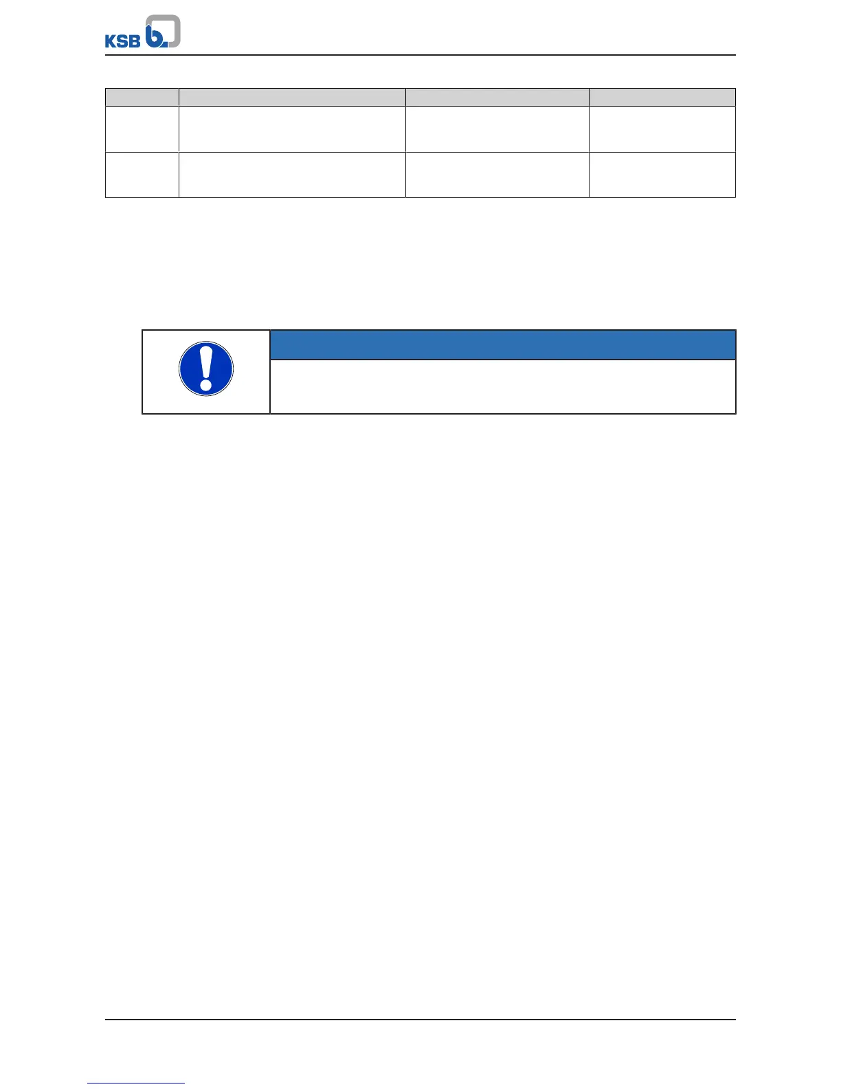
Parameter Description Possible settings Factory setting
3-8-2-3 Analog Input 2 Lower Limit Minimum limit of measuring
range (dependent on the analog
input function selected)
0
3-8-2-4 Analog Input 2 Upper Limit Maximum limit of measuring
range (dependent on the analog
input function selected)
0
It is also possible to simultaneously read 2signals via analog input1 and analog input
2 to query these signals based on the following criteria (setting only possible for
analog input 2):
▪ Difference of the two signal values DIFF (AI1, AI2)
▪ Minimum of the two signal values MIN (AI1, AI2)
▪ Maximum of the two signal values MAX (AI1, AI2)
▪ Mean value of the two signal values AVE (AI1, AI2)
NOTE
If a failure is detected at one of the two analog input signals, the process value
corresponds with the remaining signal, which can have undesirable effects on the
process.
If the analog input is configured to one of the following settings, the available
sensor signals are only used for calculations and not for control purposes.
▪ Suction Pressure_Internal
▪ Discharge Pressure_Internal
▪ Differential Pressure_Internal
For example, analog input1 uses a pressure sensor in a collecting line as the source
for control but at the same time, an additional pressure sensor is available at analog
input 2 for taking local measurements at the pump that are not meant to be used as
actual values for pump control.
▪ Suction Pressure_Internal
▪ Discharge Pressure_Internal
▪ Differential Pressure_Internal
8.10.3 Relay outputs
Operating status information can be queried on the two volt-free contacts
(changeover contact relays) of the frequency inverter.