8 Commissioning/Shutdown
117 of 212
PumpDrive 2
The Behaviour of External Message parameter (3-9-14-2) can be used to determine
whether the message is self-acknowledging or not.
The external message triggers a routine alert or a routine warning that can also be
taken into account in the general fault message via a relay.
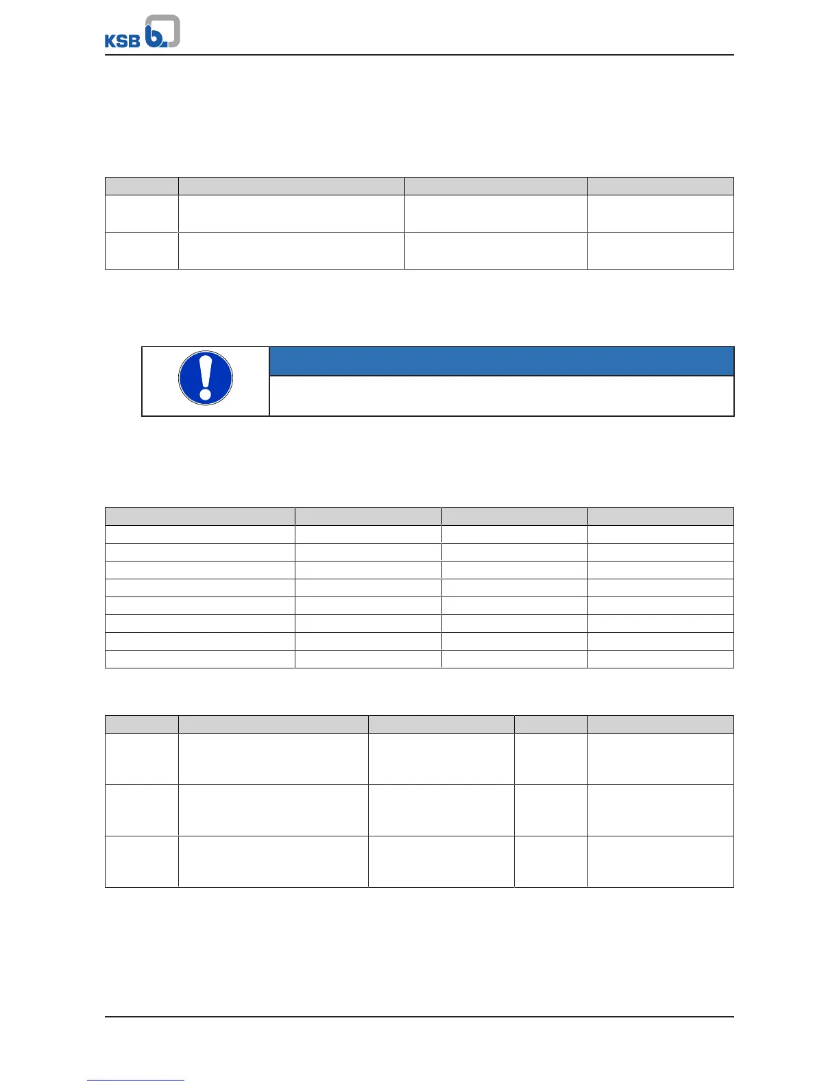
Table87: External message parameters
Parameter Description Possible settings Factory setting
3-9-14-1 Response to External Message
Response to output of external message
▪ Alert
▪ Warning
Alert
3-9-14-2 Behaviour of External Message
Alarm response of external message
▪ Non-self-acknowledging
▪ Self-acknowledging
Non-self-acknowledging
8.10.1.3 Fixed-speed operation
This function can be used to change the current speed of the frequency inverter by
specifying a fixed speed.
NOTE
Requirements for the Fixed Speed Operation function must be specified at every
control device, not just at the active master control device.
Depending on the connection of the digital inputs, up to 3 fixed speeds can be
selected. The function of the digital inputs selected is defined via Control Digital Bit
0, Control Digital Bit 1 and Control Digital Bit 2. Behaviour depends on the wiring of
the digital inputs.
Table88: Wiring of digital inputs
Control Digital Bit 2 Control Digital Bit 1 Control Digital Bit 0
OFF 0 0 0
Automatic 0 0 1
Manual (variable speed) 0 1 0
Fixed Speed 1 0 1 1
Not used 1 0 0
Fixed Speed 2 1 0 1
Not used 1 1 0
Fixed Speed 3 1 1 1
Parameters 3-6-5-1 and 3-6-5-3 are used to define the fixed speed values.
Table89: Parameters for fixed speed operation via digital inputs
Parameter Description Possible settings Refers to Factory setting
3-6-5-1 Fixed Speed 1
Fixed speed selectable via digital
inputs
Minimum to maximum
speed of motor
3-2-2-1
3-2-2-2
0
3-6-5-2 Fixed Speed 2
Fixed speed selectable via digital
inputs
Minimum to maximum
speed of motor
3-2-2-1
3-2-2-2
0
3-6-5-3 Fixed Speed 3
Fixed speed selectable via digital
inputs
Minimum to maximum
speed of motor
3-2-2-1
3-2-2-2
0
8.10.1.4 Dry running protection
Dry running can be monitored by an external sensor (e.g. pressure switch) via a
digital input. For this purpose, the digital input function must be set to the dry
running protection value.