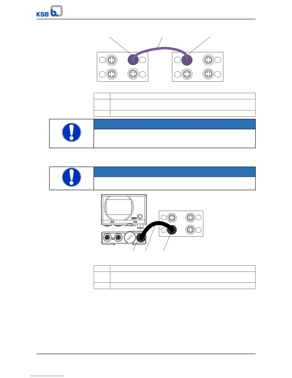
Fig.42: Connecting M12 modules in dual and multiple pump configurations
1 Connection for dual/multiple pump configuration, PumpDrive No.1
2 Pre-configured bus cable for dual and multiple pump configuration
(colour: light purple, connector: angled, connector: angled)
3 Connection for dual/multiple pump configuration, PumpDrive No.2
NOTE
Terminating resistors (refer to KSB accessories) that can be connected to the
unassigned M12 connector (C or D) at the M12 module are required for the bus
terminator.
Connecting PumpMeter in single-pump configurations
Use pre-configured cables to connect PumpMeter (ðSection12.2,Page197)
NOTE
Connect PumpMeter (Modbus) to the M12 module, input A.
Fig.43: Connecting the M12 module to PumpMeter in single-pump configurations
1 PumpMeter: Modbus connection
2 Pre-configured bus cable for connecting PumpMeter to M12 module
(colour: black, socket: straight, connector: angled)
3 M12 module: Connection for PumpMeter (Modbus)
Connecting PumpMeter in dual and multiple pump configurations
Pre-configured crosslink cables can be used to switch the PumpMeter Modbus signal
from frequency inverter to frequency inverter. (ðSection12.2,Page197)