7 Installation at Site
60 of 212
PumpDrive 2
CAUTION
Differences in potential
Damage to the frequency inverter!
▷ Never connect an external +24 V DC voltage source to a digital input.
Analog outputs
▪ The frequency inverter is equipped with an analog output whose output value
can be parameterised via the control panel.
▪ Analog signals to a higher-level control station must be electrically isolated when
they are transmitted, for example by using isolating amplifiers.
Relay outputs
▪ The function of the two volt-free relays (NO/NC) can be parameterised via the
control panel.
Analog inputs
▪ Analog signals from a higher-level control station must be electrically isolated
when they are transmitted to the frequency inverter, for example by using
isolating amplifiers.
▪ If the sensor signal from a higher-level control system or a PLC is transmitted to
the frequency inverter, the reference signal (e.g. sensor GND) should also be
carried in the same line. The sensor and reference signals can then be optimally
connected to the differential inputs of the frequency inverter.
▪ If an external voltage or current source is used for the analog inputs, the ground
of the setpoint or sensor sources is applied to terminal B1 or B5.
▪ The +24V DC voltage source (terminal B4 or B8) serves as a power supply for the
sensors connected to the analog inputs.
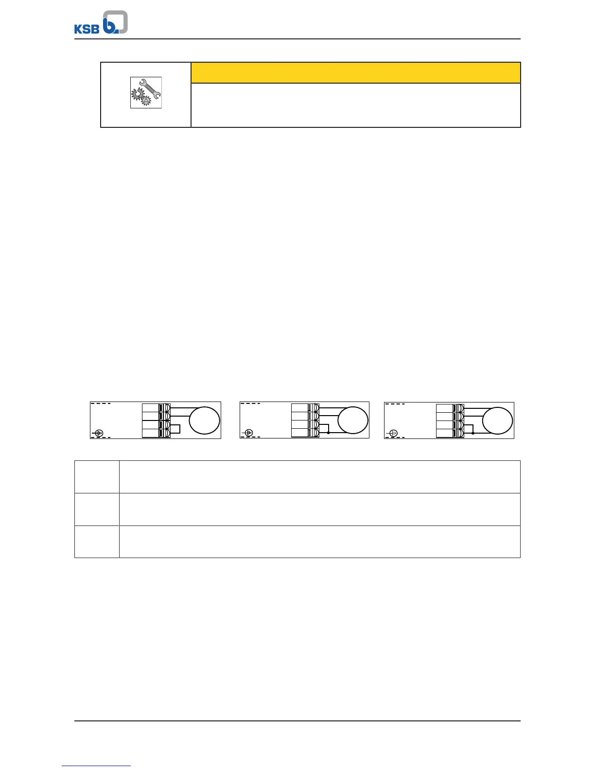
▪ The two differential analog inputs are connected as follows:
– The sensor signal is connected to AIN1+ (terminal B3) or AIN2+ (terminal B7).
– The reference signal (0V of sensor) is connected to AIN1- (terminal B2) or
AIN2- (terminal B6).
Fig.54: Connecting sensors to the differential analog input
a) Current sensor
Output signal: 0/4 - 20mA
2-wire
b) Current sensor
Output signal: 0/4 - 20mA
3-wire
c) Voltage sensor
Output signal: 0/2 - 10V
3-wire