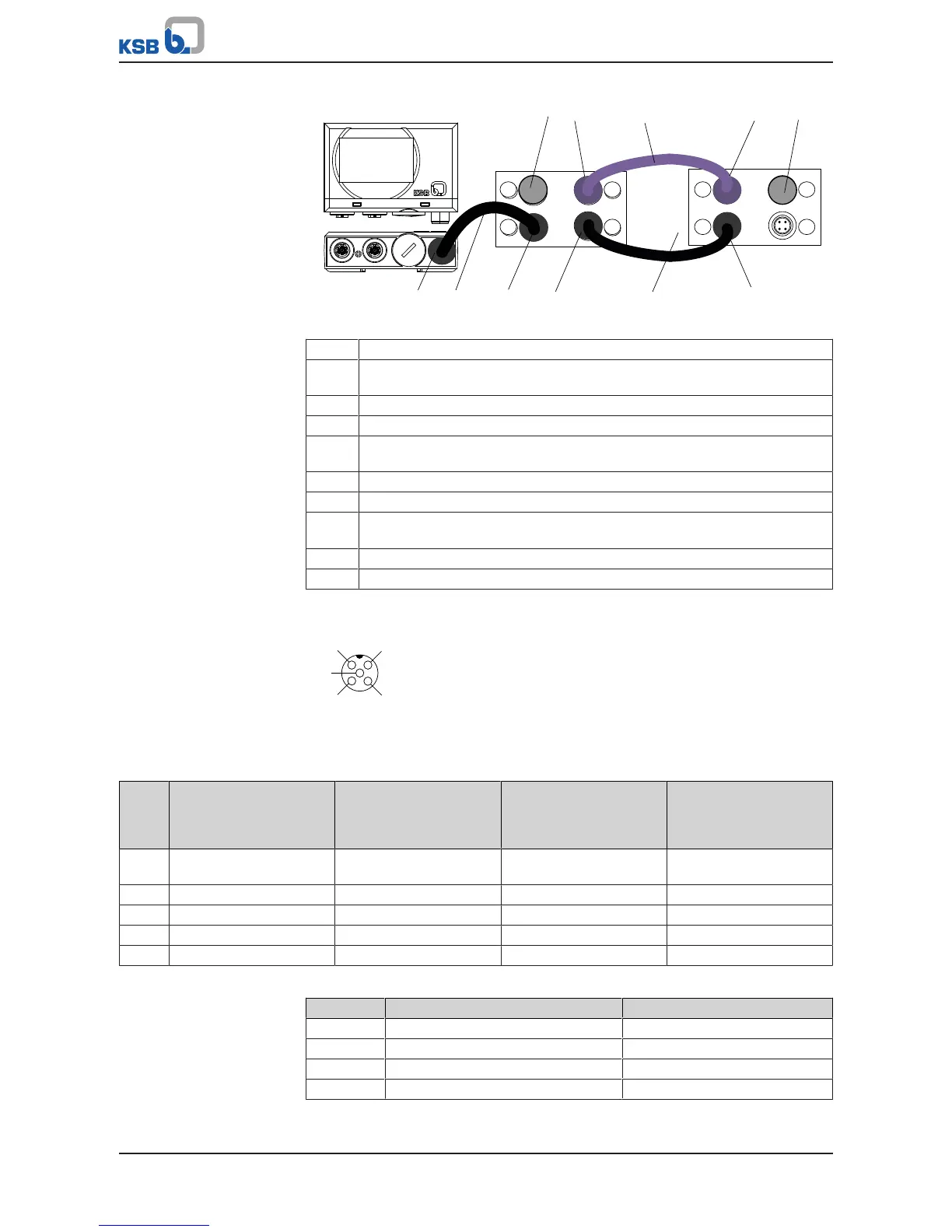
Fig.44: Connecting PumpMeter in dual and multiple pump configurations
1 PumpMeter: Modbus connection
2 Pre-configured bus cable for connecting PumpMeter to M12 module
(colour: black, socket: straight, connector: angled)
3 M12 module, socket A: Connection for PumpMeter (Modbus)
4 M12 module, socket B: Connection for bus cable crosslink (Modbus)
5 Pre-configured bus cable crosslink for redundant connection of PumpMeter
(colour: black, connector: angled; connector: angled)
6 M12 module, socket A: Connection for bus cable crosslink (Modbus)
7 Connection for dual/multiple pump configuration, PumpDrive No.1
8 Pre-configured bus cable for dual and multiple pump configuration
(colour: light purple, connector: angled, connector: angled)
9 Connection for dual/multiple pump configuration, PumpDrive No.2
10 Terminating resistor
Pin assignment
Fig.45: M12 module standard assignment for M12 socket as viewed looking at the
mating face
Table31: Pin assignment, M12 module, input A/B
Pin Conductor colour coding M12 socket A assignment
parameterised for
PumpMeter Modbus
M12 socket B assignment
parameterised for
PumpMeter Modbus
M12 socket A and B
assignment
parameterised as analog
input
1 Brown 24 V output (supply to
PumpMeter)
24 V output (supply to
PumpMeter)
24 V output (supply to
PumpMeter)
2 Blue 0V 0 V 0 V
3 White D- D+ Input (4 - 20 mA)
4 Grey D+ D- -
5 - - - Vent opening
Table32: Pin assignment, M12 module, input C/D
Pin Conductor colour coding M12 socket C and D assignment
1 - Shielding
2 Red -
3 Black CAN GND
4 White CAN H