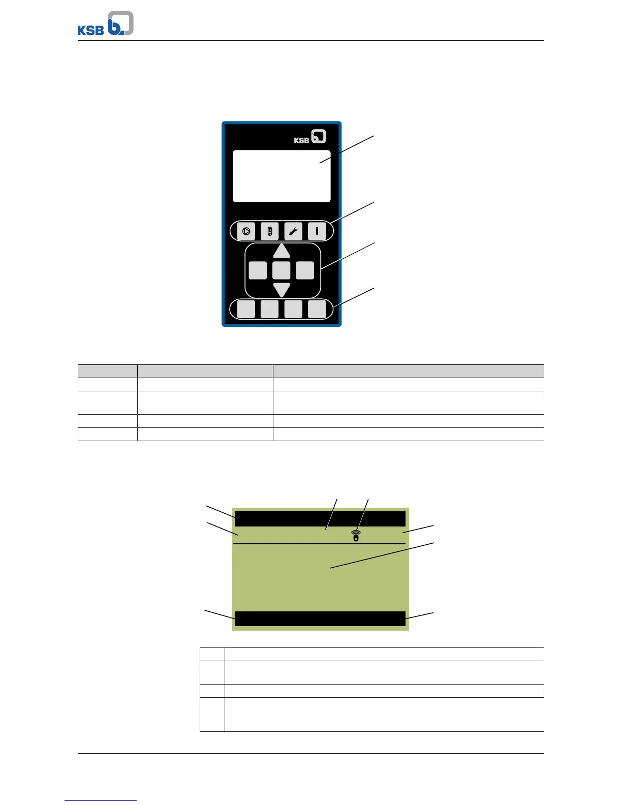
Fig.6: Graphical control panel
Table8: Description of graphical control panel
Position Description Function
1 Graphical display Displays information on frequency inverter operation
2 Menu keys Accessing the elements of the first menu level (Operation,
Diagnosis, Settings and Information)
3 Navigation keys Navigation and parameter setting
4 Operating keys Toggling operating modes
4.1.1 Graphical display
The main screen breaks down into 6areas.
Fig.7: Main screen (example)
1 Motor standstill heater is switched on
2 The wireless icon illuminates when the Bluetooth module is inserted. The
wireless icon flashes when communication takes place.
3 Display of the master and login level
4 Display of up to four (4)operating values: One operating value is displayed in
large format. Three (3) operating values are displayed in small format. The
operating values scroll through cyclically.