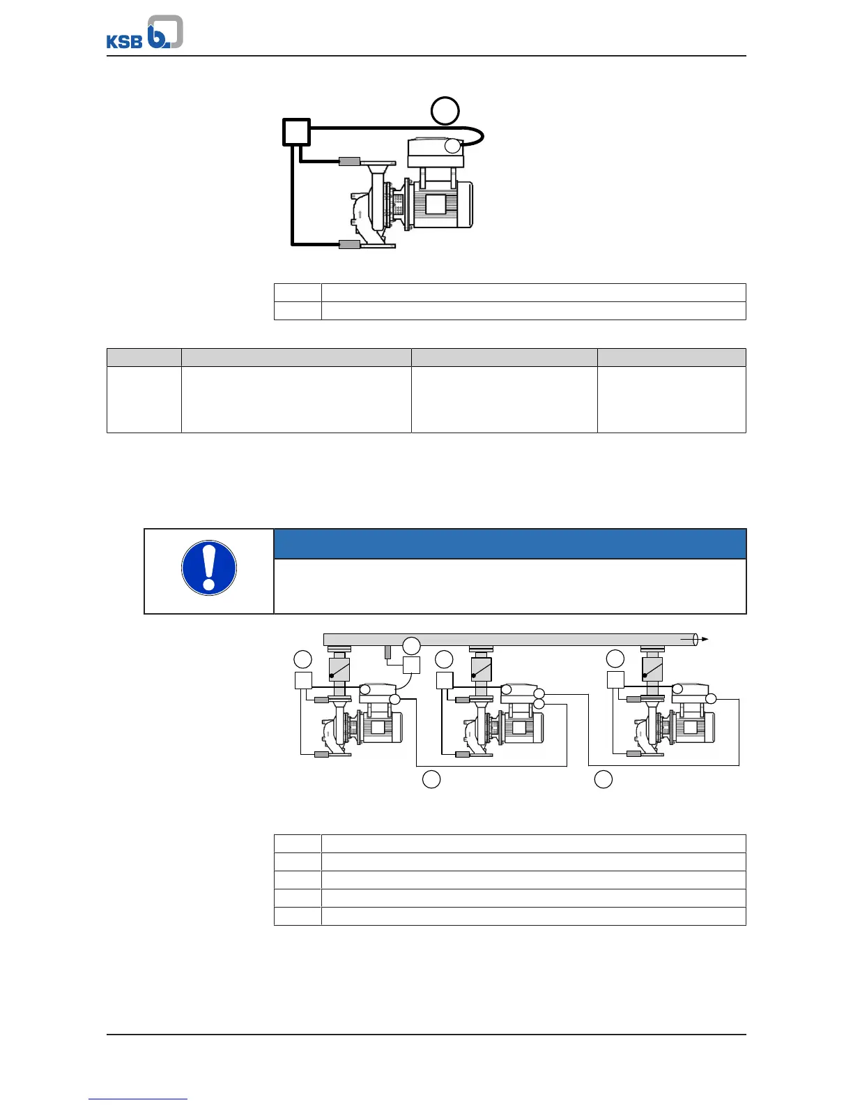
Fig.81: PumpMeter as actual value source via Modbus
1 PumpMeter as actual value source
2 PumpMeter connection to the M12 module, inputA, via Modbus
Table103: PumpMeter connection via Modbus
Parameter Description Possible settings Factory setting
3-8-4-1 Function M12 Module Input A
Function of M12 module, inputA. Internal
operating values cannot be used as an
actual value source.
PMtr Suction/Discharge Pressure OFF
Parameterising the M12 module for PumpMeter as an internal measured variable
(via Modbus)
If PumpMeter is only used as an internal measured variable at inputA of the M12
module (via Modbus) and not for control, the Function M12 Module Input A
parameter (3-8-4-1) must be set to PMtr Suction / Discharge Pressure.
NOTE
When changing parameter 3-8-4-1 to the above-mentioned value (in particular in
retrofit applications) a 24 V voltage reset is triggered, which is required for
initialisation of the bus connection to PumpMeter.
Fig.82: PumpMeter as internal measured variable per pump, external pressure sensor
as actual value source
1 External pressure sensor as actual value source
2 PumpMeter as internal measured variable for the master control device
3 PumpMeter as internal measured variable for auxiliary control device1
4 PumpMeter as internal measured variable for auxiliary control device2
5 Pre-configured cable for multiple pump configuration