8 Commissioning/Shutdown
122 of 212
PumpDrive 2
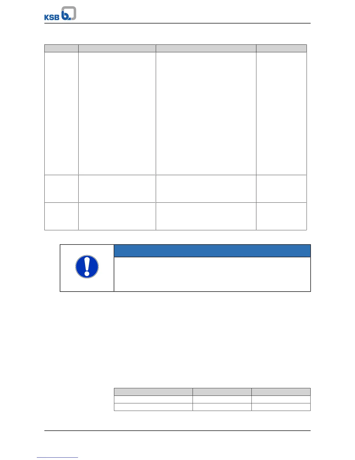
Table94: Parameters for relay2
Parameter Description Possible settings Factory setting
3-8-10-1 Relay 2 Function
Selectable messages via relay 2
▪ None
▪ AUTO operating mode
▪ RUN operating status
▪ AUTO/SLEEP operating status
▪ Warning
▪ Alert
▪ Alarm or warning
▪ Dynamic overload protection
▪ Current too high
▪ Current too low
▪ Frequency too high
▪ Frequency too low
▪ Power too high
Power too low
▪ Actual value = setpoint
RUN operating
status
3-8-10-2 Time Delay ON
Period of time during which the
event selected must be continually
available until the relay is set
0,0…10,0 s 0,5 s
3-8-10-3 Time Delay OFF
Period of time for which the event
selected must have gone before
the relay is reset
0,0 …10,0 s 0,5 s
Actual Value = Setpoint function
NOTE
The parameter values and value ranges/units entered are mutually dependent. This
is why the first step in parameterising the frequency inverter is always to specify the
applicable value range and units (refer to parameter 3-11). If the value range or
unit is subsequently changed, all dependent parameters must be checked for
correctness again.
For the Actual Value = Setpoint function, after the value range and units are defined,
the bandwidth must be specified for comparing the actual value and setpoint data.
This is done via the Deviation Permitted when Actual Value = Setpoint (3-6-4-7)
parameter.
8.10.4 Analog outputs
By default, the value selected via parameter 3-8-7-1 (Assignment1, Analog Output1)
is output as a 4 - 20mA signal at the analog output. .
Four different process values can be assigned to the analog output.
The selection as to which value is output is made via two digital inputs (2 bits =
4options). For this purpose, parameterise the function of the digital inputs to
Control AOUT Bit 0 or Control AOUT Bit 1.
Table95: Controlling the output values
Assignment at analog output 1 Control AOUT Bit 1 Control AOUT Bit 0
1 0 0
2 0 1