7 Installation at Site
37 of 212
PumpDrive 2
When installing the power components in the control cabinet, make sure they are
not too close to other devices (control and monitoring devices).
Maintain a minimum distance of 0.3metres between the cabling and power
components as well as other cabling in the control cabinet.
Connecting cables
Use different earth bus bars for the control cable and power/motor connection cable.
The shield on the power/connection cable must consist of a single piece and be
earthed at both ends either just on the appropriate earth terminal or on the earth
bus bar (do not connect it to the earth bus bar in the control cabinet).
The shielded cable ensures that the high-frequency current, which normally flows as
a discharge current from the motor housing to earth or between the individual
conductors, now flows through the shielding.
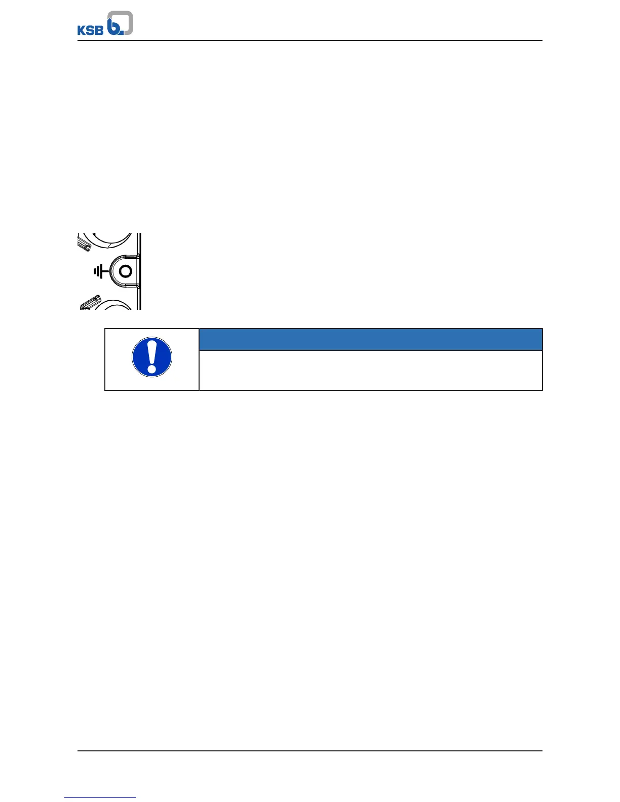
The shield for the control cable (connection on frequency inverter side only) also
serves as protection against radiated emissions and must be connected to the
designated connection points in the control cable terminal housing.
Fig.16: Connecting a shield
In applications with long shielded motor cables, additional reactive resistors or
output filters must be provided to compensate the capacitive stray current to earth
and reduce the rate of voltage rise on the motor. These measures help reduce radio
frequency interference further. Using just ferrite rings or reactive resistors does not
ensure compliance with the limit values defined in the EMC directive.
NOTE
If you are using shielded cables that are longer than 10 m, check the stray
capacitance to ensure that the diffusion between the phases or to earth is not
excessive, which could cause the frequency inverter to stop.
Routing cables
Route control cable and power/motor connection cable in separate cable ducts.
When routing the control cable observe a minimum distance of 0.3metres between
the control cable and the power/motor connection cables.
If you cannot avoid crossing control and power/motor connection cables, you should
cross them at 90degrees to each other.
7.4.2.4 Earth connection
The frequency inverter must be properly earthed.
To ensure greater interference immunity, a wide contact face is required for the
different earth connections.
In the case of cabinet mounting, use two separate copper earth bus bars (mains
power supply/motor connection and control connection bar) with a suitable size and
cross-section for earthing the frequency inverter. All the earth connections are
connected to these.
The bars are connected to the earthing system at one point only.
The control cabinet is then earthed via the mains earthing system.
7.4.2.5 Line chokes
The line input currents indicated are for orientation only; they refer to operation at
nominal rating. These currents may vary depending on the actual line impedance. In
low-impedance mains, higher currents may occur.
To limit the line input current, external line chokes can be used alongside the line
chokes already integrated (in the power range up to and including 45 kW). Line
chokes also reduce mains feedback and improve the power factor. The scope of
DINEN 61000-3-2 must be heeded.
Appropriate line chokes are available from KSB. (ðSection12.2.8,Page205)