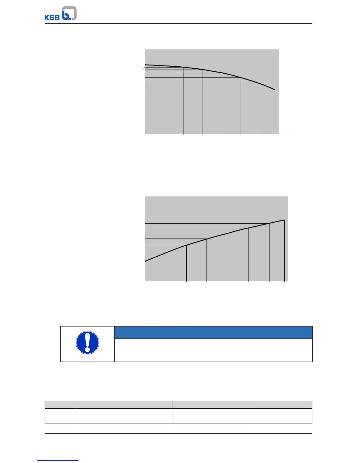
Fig.63: Characteristic head curve with seven data points and the relevant parameters
Flow rate Q
0
, i.e. parameter (3-4-3-1), is always zero. Flow rate Q6 (3-4-3-7) describes
the end of the characteristic curves and also represents the maximum permissible
flow rate of the pump.
Fig.64: Power curve with seven data points and the relevant parameters
The same flow rate values are used for the power curves as for the characteristic
head curve.
NOTE
The power curve is not converted to account for the density of the fluid handled
(3-5-1). A power curve that is consistent with the density of the fluid handled must
therefore be entered.
The optimum operating point of the pump at nominal speed is defined via the Flow
Rate Q
opt
parameter (3-4-3-8). The low flow limit of the pump at nominal speed is
defined via the Low Flow Limit Flow Rate parameter (3-4-3-30). This is a percentage-
based specification that refers to the optimum operating point.
Table61: Parameters for matching PumpDrive to the pump
Parameter Description Possible settings Factory setting
3-4-3-1 Flow Rate Q_0 Minimum to maximum flow rate Pump-specific
3-4-3-2 Flow Rate Q_1 Minimum to maximum flow rate Pump-specific