8 Commissioning/Shutdown
72 of 212
PumpDrive 2
Table46: Parameter for setpoint or control value via field bus module
Parameter Description Possible settings Refers to Factory setting
3-6-2 Control Point
Toggling the control point from
Local to Field Bus. DIGIN/ANIN
have the highest priority. The
actual value source must be
configured separately.
▪ Local
▪ Field Bus
- Local
8.7 Pump operation
8.7.1 Single-pump operation
8.7.1.1 Open-loop control mode
Open-loop control mode is selected via the Type of Control parameter(3-6-1) for
pumps in automatic mode (AUTO key). In open-loop control mode, the pump is
operated at the specified speed. This speed is specified using the Control Value
(Open-loop Control) parameter 1-3-3 (ðSection8.7.1.1.2,Page73) or via an analog
input (ðSection8.7.1.1.1,Page72) .
The frequency inverter starts in automatic mode if digital input 1 is supplied with
+24V DC (terminal strip C2/C1) (ðSection8.10.1,Page114) or the system start is
activated via the System Start/ Stop parameter (1-3-1).
8.7.1.1.1 Open-loop control mode using external standard signal
NOTE
The parameter values and value ranges/units entered are mutually dependent. This
is why the first step in parameterising the frequency inverter is always to specify the
applicable value range and units (refer to parameter 3-11). If the value range or
unit is subsequently changed, all dependent parameters must be checked for
correctness again.
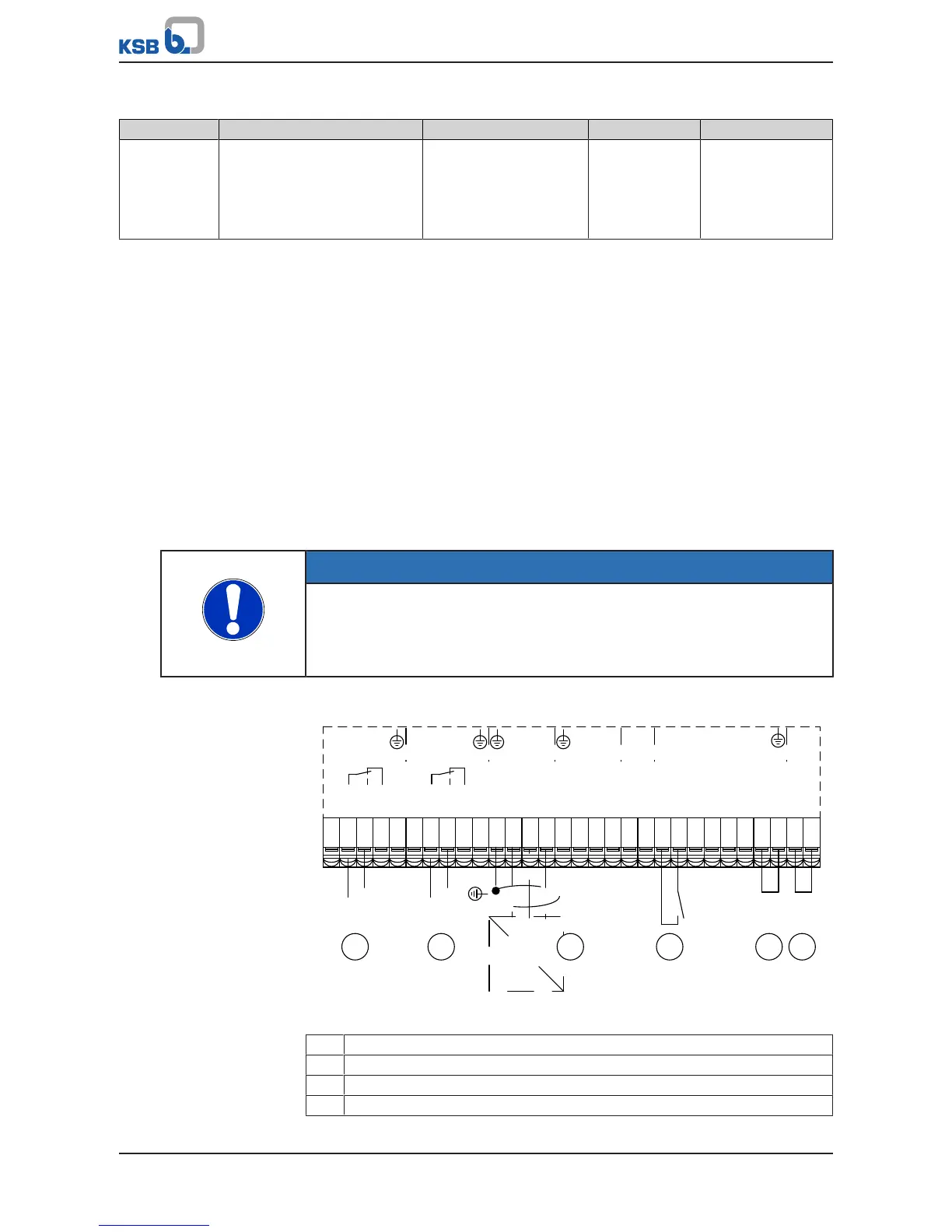
A control value can be defined in automatic mode using an external standard signal.
Fig.57: Terminal wiring diagram, open-loop control mode (dashed line = optional)
1 Start / Stop
2 External setpoint signal (ðSection8.6,Page70)
3 Signal relay 1 (ðSection8.10.3,Page120)
4 Signal relay 2 (ðSection8.10.3,Page120)