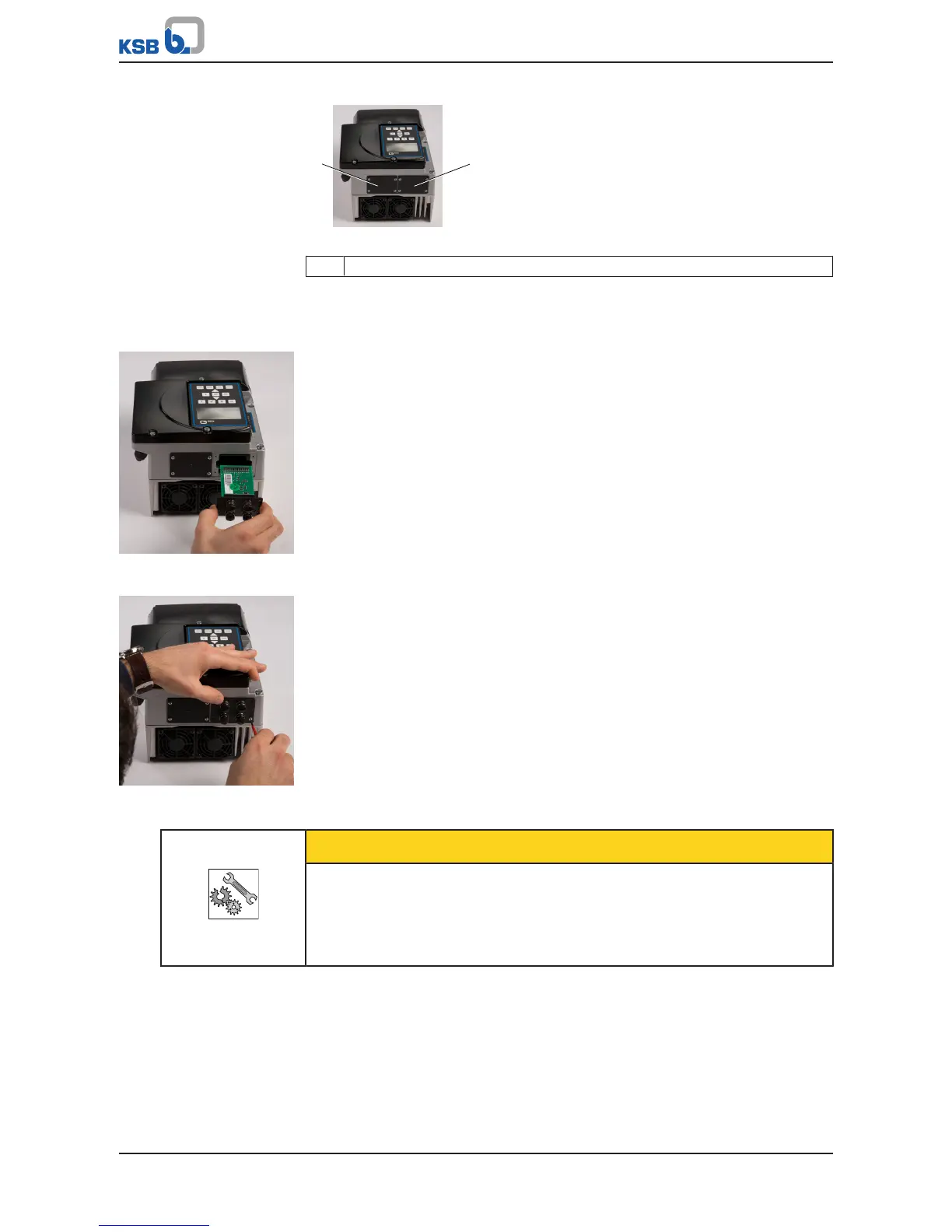
Fig.39: Blind cover
1 Blind cover
1. Unscrew the cross recessed head screws in the blind cover.
2. Remove the blind cover.
M12 module
Fig.40: Inserting the M12
module
1. Carefully insert the M12 module in the open slot. The M12 module is guided on
rails until it engages in the contact.
Fig.41: Securing the M12
module
2. Secure the M12 module using the 4 cross recessed head screws. IP55 enclosure
protection is not provided until the screws have been tightened.
CAUTION
Incorrect assembly
Impairment of protection provided by the enclosure (protection may be
compromised)!
▷ Cover unused M12 sockets of the M12 module with a cap (included in the scope
of supply).
Connecting dual and multiple pump configurations
Designing dual and multiple pump configurations via a cable pre-configured
especially for this connection (see Accessories)