8 Commissioning/Shutdown
111 of 212
PumpDrive 2
Table79: Operating ramp parameters
Parameter Description Possible settings Factory setting
3-3-5-3 Operating Ramp Time
Time defining the ramps for speed
changes in open-loop control mode or in
manual mode
1 - 600 s 3s
3-2-2-2 Maximum Motor Speed 3-2-2-1…3-11-1-2¹ Motor-specific
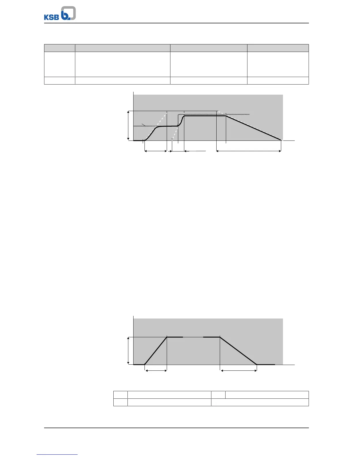
Fig.79: Example speed curve in open-loop control mode
The illustration shows, by example, a speed curve in open-loop control mode as a
solid line. The control value (speed setting) is displayed as a dotted line. The start
command takes effect at time 2. The speed increases along the start ramp until the
control value (1) is reached and maintained. The control value increases
spontaneously at time3. The speed increases along the operating ramp until the
increased control value is reached and maintained. The stop command takes effect at
time 4. The speed decreases along the stop ramp until the machine comes to a
standstill.
Setpoint ramp (closed-loop control mode)
In closed-loop control mode, setpoint changes are made along the setpoint ramp.
This, in turn, avoids spontaneous changes in speed and system oscillations. The
inclination of the setpoint ramp is defined by parameter 3-6-4-6 and control range Δx
as shown in Figure 4. Control range Δx results from Type of Control 3-6-1 and the
settings in the Value Ranges and Units menu 3-11. Two examples:
Example 1
Control targets constant discharge pressure:
The Type of Control parameter (3-6-1) is set to Discharge Pressure. Accordingly,
control range Δx is limited by the Minimum Pressure (3-11-2-1) and Maximum
Pressure (3-11-2-2) parameters.
Example 2
Control targets constant temperature:
The Type of Control parameter (3-6-1) is set to Temperature (Heating). Accordingly,
control range Δx is limited by the Minimum Temperature (3-11-4-1) and Maximum
Temperature (3-11-4-2) parameters.