8 Commissioning/Shutdown
65 of 212
PumpDrive 2
8.2 Control point concept
Possible control points are the control panel, digital/analog inputs, field buses, radio
remote control or the Service Tool. These control points are grouped into three
categories:
▪ Based on one-off event: Control panel, radio remote control, Service Tool
▪ Based on cyclic events: Field buses
▪ Based on permanent/continuous state: Digital/analog inputs
The following control functions can be realised via a control point:
▪ System Start / Stop
▪ Setpoint in closed-loop control mode, also alternative setpoint
▪ Control value in open-loop control mode, also alternative control value
▪ Control value in manual mode
▪ Toggling individual frequency inverters between Manual, OFF and Automatic
▪ Toggling between normal and alternative setpoint/control value
The Control Point parameter (3-6-2) only distinguishes between field bus and local
operation (control panel, radio remote control or Service Tool).
Digital and analog inputs
Digital and analog inputs are treated in a special manner:
A digital or analog input can be configured for each of the control functions
mentioned. Digital and analog inputs have the highest priority. For this type of
control, all other control points (e.g. control panel) are disabled, even if the control
function is configured for a field bus. When the control point is changed, the values
last set remain intact until they are also changed.
Specifications for digital and analog inputs are defined at the active master control
device (= master). Exceptions are fixed speeds, as well as the Digital Potentiometer
Manual and OFF parameter options, which only apply to the respective control
function.
8.3 Setting motor parameters
The motor parameters are typically preset at the factory. The factory default motor
parameters must be compared with the data provided on the motor name plate and
adjusted, if required.
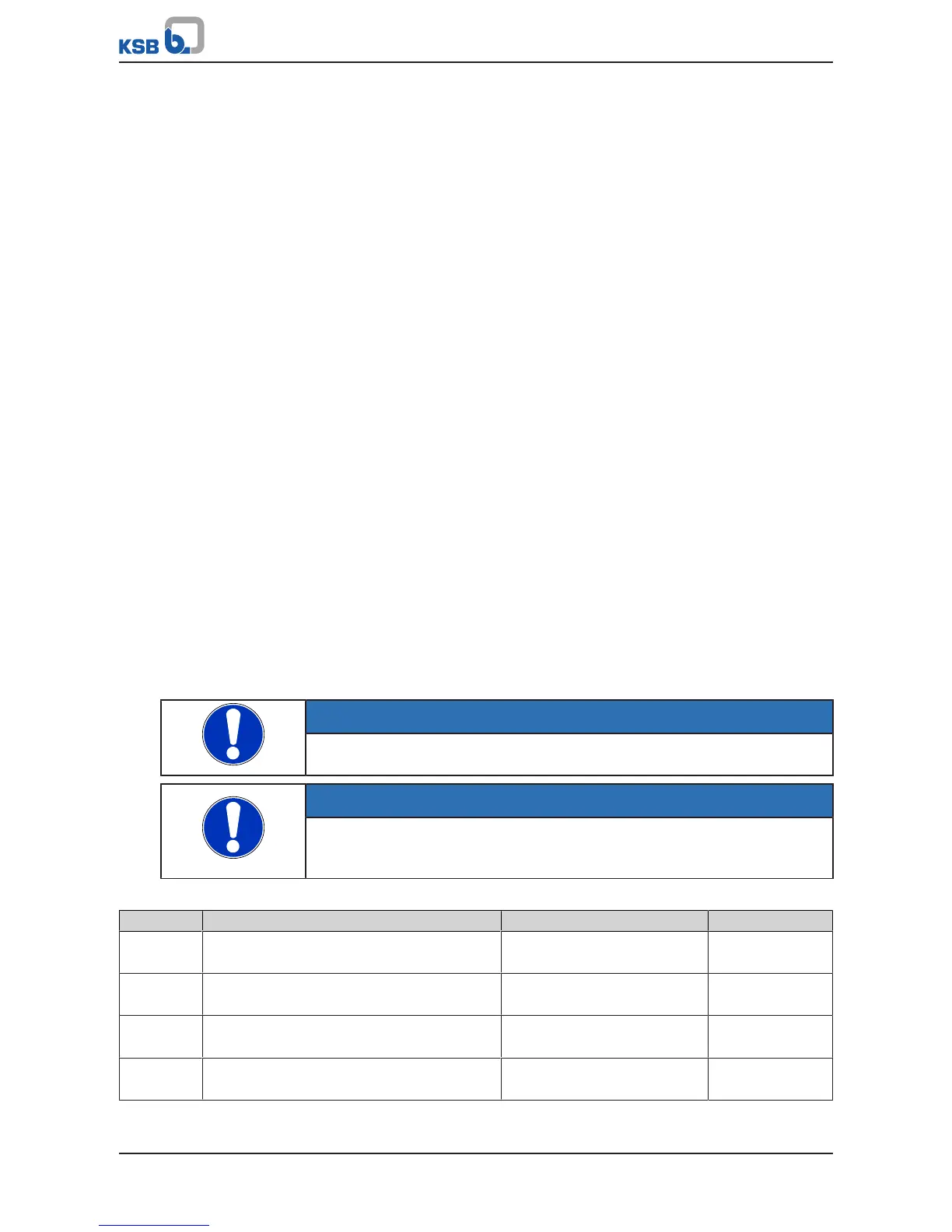
NOTE
Motor parameters cannot be changed while the motor is in operation.
NOTE
If the motor parameters are changed, the Automatic Motor Adaptation function
must be subsequently called up in conjunction with the vector control method
(Motor Control Method parameter 3-3-1).
Table38: Motor parameters
Parameter Description Possible settings Factory setting
3-2-1-1 Nominal Motor Power
Nominal power of motor as per name plate
0,00…110,00 kW Dependent on size/
motor
3-2-1-2 Nominal Motor Voltage
Nominal voltage of motor as per name plate
400…460 V Dependent on size/
motor
3-2-1-3 Nominal Motor Frequency
Nominal frequency of motor as per name plate
0,0…200,0 Hz Dependent on size/
motor
3-2-1-4 Nominal Motor Current
Nominal current of motor as per name plate
0,00…150,00 A Dependent on size/
motor