7 Installation at Site
49 of 212
PumpDrive 2
If longer connection cables than those listed above are required or the connection
cable's stray capacitance value exceeds the above values, we recommend installing a
suitable output filter between the frequency inverter and the motor to be controlled.
These filters reduce the voltage ramp-up time of the frequency inverter output
voltages and limit their peaks.
1. Install a line choke in series (in the power cable) upstream of the frequency
inverter.
2. Install an output filter in series in the motor connection cable downstream of
the frequency inverter.
7.4.3.4 Establishing an earth connection
The frequency inverter must be earthed.
Observe the following when establishing the earth connection:
▪ Ensure that the cable lengths are as short as possible.
▪ Use different earth bus bars for the control and power/motor connection cables.
▪ The earth bus bar of the control cable must not be affected by currents from the
power/motor connection cables since this could be a source of interference.
Connect the following to the earth bus bar of the power/motor connection cable:
▪ Motor earthing connections
▪ Housing of the frequency inverter
▪ Shielding of the power/motor connection cable
Connect the following to the earth bus bar of the control cable:
▪ Shielding of the analog control connections
▪ Shielding of the sensor cables
▪ Shielding of the field bus connection cable
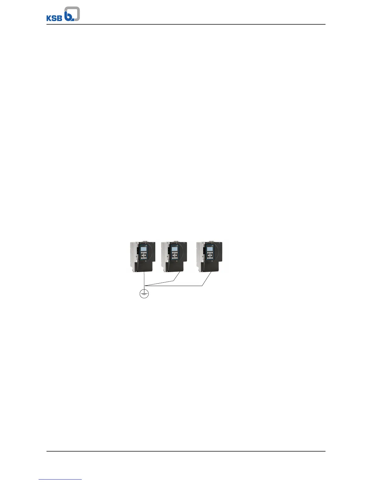
Installing multiple
frequency inverters
Fig.37: Establishing an earth connection
If you are installing more than one frequency inverter, the star configuration is
recommended.
7.4.3.5 Installing and connecting the M12 module
The M12 module can be used to connect multiple frequency inverters to implement
dual or multiple pump configurations. The M12 module also allows PumpMeter to be
connected to the frequency inverter via Modbus.