7 Installation at Site
57 of 212
PumpDrive 2
Installing the I/O extension board
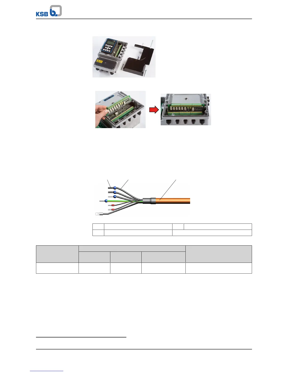
Fig.50: C-shaped housing cover
1. Remove C-shaped housing cover. (ðSection7.4.3.1,Page38)
Fig.51: Installing the I/O extension board
2. Connect the I/O extension board to the control PCB via the guide rails on the
housing.
3. Connect the control cables (ðSection7.4.3.8,Page57) .
4. Reconnect the C-shaped housing cover.
7.4.3.8 Connecting the control cable
Fig.52: Structure of electric cable
1 Wire end sleeve 2 Core
3 Cable
Table34: Cable cross-section, control terminals
Control terminal Core cross-section [mm²] Cable diameter
13)
[mm]
Rigid cores Flexible cores Flexible cores with
wire end sleeves
Terminal strip A, B, C 0,2-1,5 0,2-1,0 0,25-0,75 M12: 3,5-7,0
M16: 5,0-10,0
13) Impairment of protection provided by enclosure when cable diameters other than those specified are used.