7 Installation at Site
56 of 212
PumpDrive 2
Connecting the field bus module
Observe the following when connecting the field bus module:
▪ Before the bus connection is established among the nodes, potential equalisation
must have been implemented and checked.
▪ To ensure high-frequency shielding, use suitable, shielded cables for the
respective field bus and install them in accordance with EMC requirements.
▪ A minimum distance of 0.3metres is recommended between such cables and
other electric conductors.
▪ Do not use the bus cable to make any further connections in addition to the field
bus module (for example, 230 V alert and 24 V start).
CAUTION
Incorrect installation
Damage to the field bus module!
▷ Never supply the field bus module with voltage using the M12 connector or the
M12 socket.
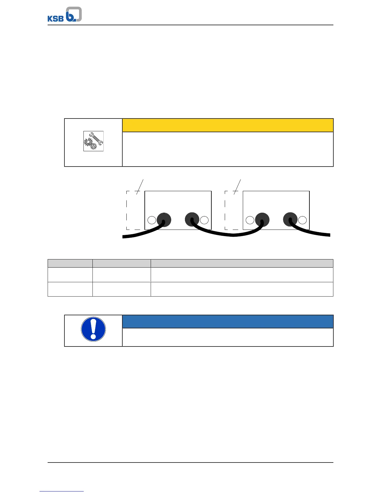
Fig.49: Connecting the field bus module
Table33: Connecting the field bus module
Item Design M12 connector
1 Frequency inverter 1 M12 connector A: Coming
M12 socket B: Going
2 Frequency inverter 2 M12 connector A: Coming
M12 socket B: Going
Field bus control must be activated in the frequency inverter when using the field bus
module (ðSection8.12,Page130) .
NOTE
The frequency inverter is reset when a field bus module is replaced or retrofitted.
Menu 3-12 for setting the parameters of the field bus module is then enabled.
7.4.3.7 Installing and connecting the I/O extension board
Additional inputs and outputs are made available by the I/O extension board:
▪ 1 analog input/PT1000
▪ 1 analog output
▪ 3 digital inputs
▪ 2 digital outputs
▪ 1 changeover contact relay
▪ 5 NO contact relays
The I/O extension board can be pre-installed at the factory or retrofitted as an
accessory.