7 Installation at Site
62 of 212
PumpDrive 2
CAUTION
Differences in potential
Damage to the frequency inverter!
▷ Never connect an external +24V DC voltage source to a digital input.
Analog outputs
▪ The I/O extension board is equipped with an analog output whose output
variable can be parameterised via the control panel.
▪ Analog signals to a higher-level control station must be electrically isolated when
they are transmitted, for example by using isolating amplifiers.
Relay outputs
▪ The I/O extension board has one volt-free (NO/NC) relay and five volt-free (NO)
relays.
▪ The function of the relays can be parameterised via the control panel.
Analog inputs
▪ Analog signals from a higher-level control station must be electrically isolated
when they are transmitted to the frequency inverter, for example by using
isolating amplifiers.
▪ If an external voltage or current source is used for the analog inputs, the ground
of the setpoint or sensor sources is applied to terminal E7.
▪ The +24V DC voltage source (terminal E10) serves as a power supply for the
sensors connected to the analog inputs.
▪ The two differential analog inputs are connected as follows:
– The sensor signal is connected to AIN3+ (terminal E9).
– The reference signal (0V of sensor) is connected to AIN3- (terminal E8).
7.4.3.9 Connecting the control panel
CAUTION
Electrostatic charging
Damage to the electronics!
▷ Personnel must ensure that they are free of electrostatic charges before the
control panel is opened (in the event that the wireless module is retrofitted).
Mounting the graphical control panel to the frequency inverter
The display is connected via an M12 plug-type connector and fixed using a C-shaped
cover.
1. Undo the screws on the C-shaped housing cover. Remove the display.
2. Position the graphical control panel and screw on the C-shaped housing cover.
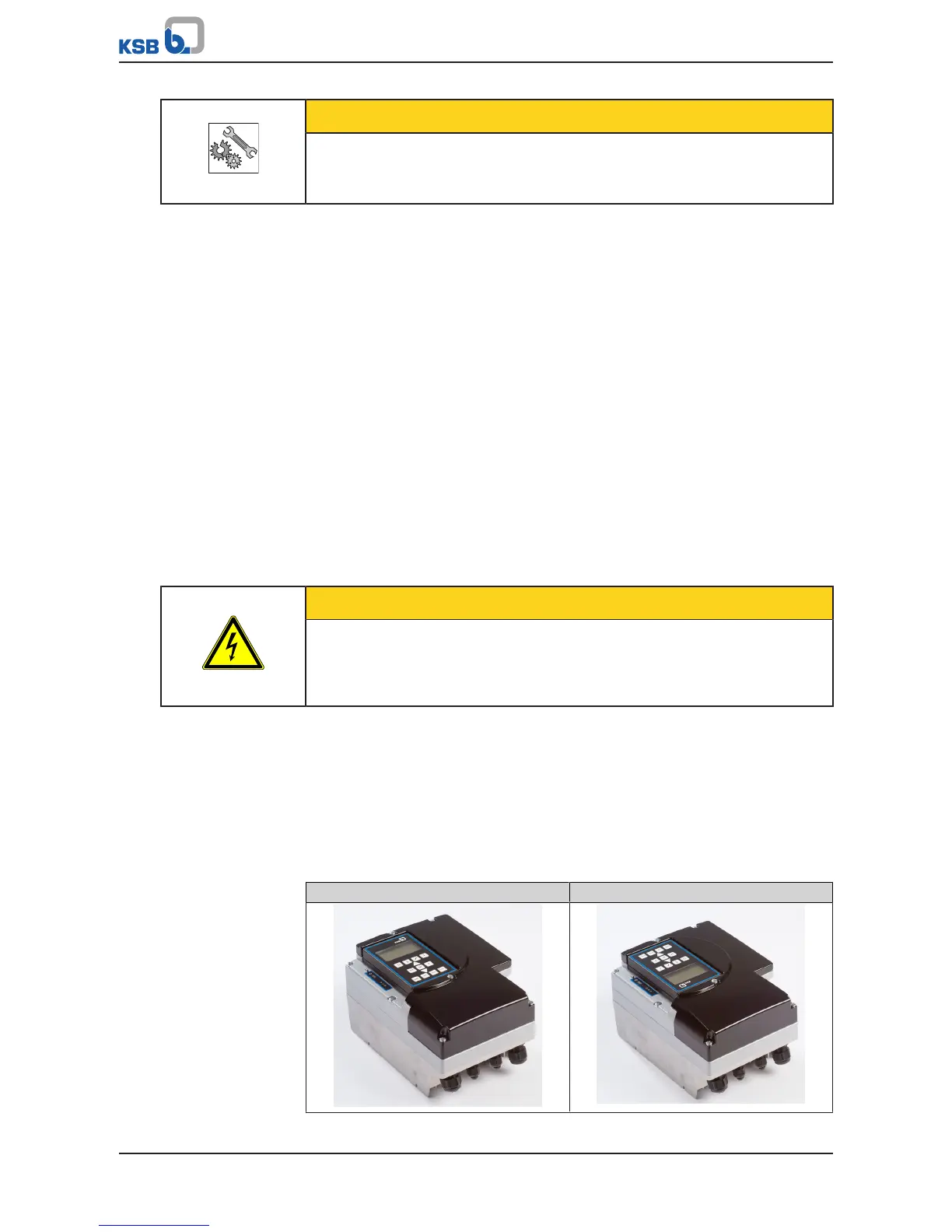
Changing the installation position of the control panel
Table37: Possible installation positions for the control panel
Standard Rotated 180°