7 Installation at Site
63 of 212
PumpDrive 2
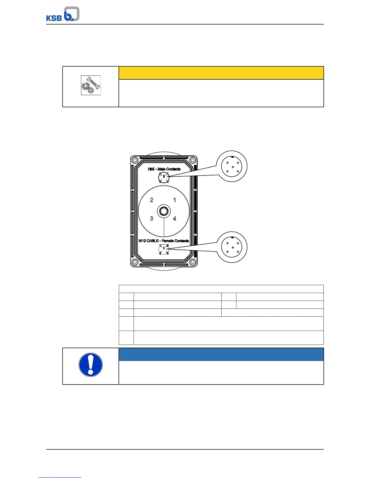
The graphical control panel can be rotated 180degrees if required. The pin
assignment of the M12 connector accommodates both installation positions.
Mounting the graphical control panel separately from the frequency inverter
CAUTION
Incorrect pin assignment
Damage to the frequency inverter and/or control panel!
▷ Assign pins as described in the operating manual.
The control panel can also be mounted separately from the frequency inverter, such
as on a wall (ðSection12.2.4,Page199) . When connecting the M12 connection
cable between the control panel and frequency inverter, ensure that the correct
connection (pin assignment) is made. The connector is not protected against reverse
polarity.
Fig.55: Pin assignment for M12 connection cable and control panel
Conductor colour coding to EN50044
1 Brown 2 White
3 Blue 4 Black
5 Grey
A Standard assignment for device connectors/cable connectors (as viewed
looking at the mating face)
B Standard assignment for device socket/cable socket (as viewed looking at the
mating face)
NOTE
If the control panel is removed during operation and at the same time, the power
supply to the DI EN is severed at the internal 24V supply line, the frequency
inverter is deactivated.