12 Purchase Order Specifications
200 of 212
PumpDrive 2
Description Design Mat. No. [kg]
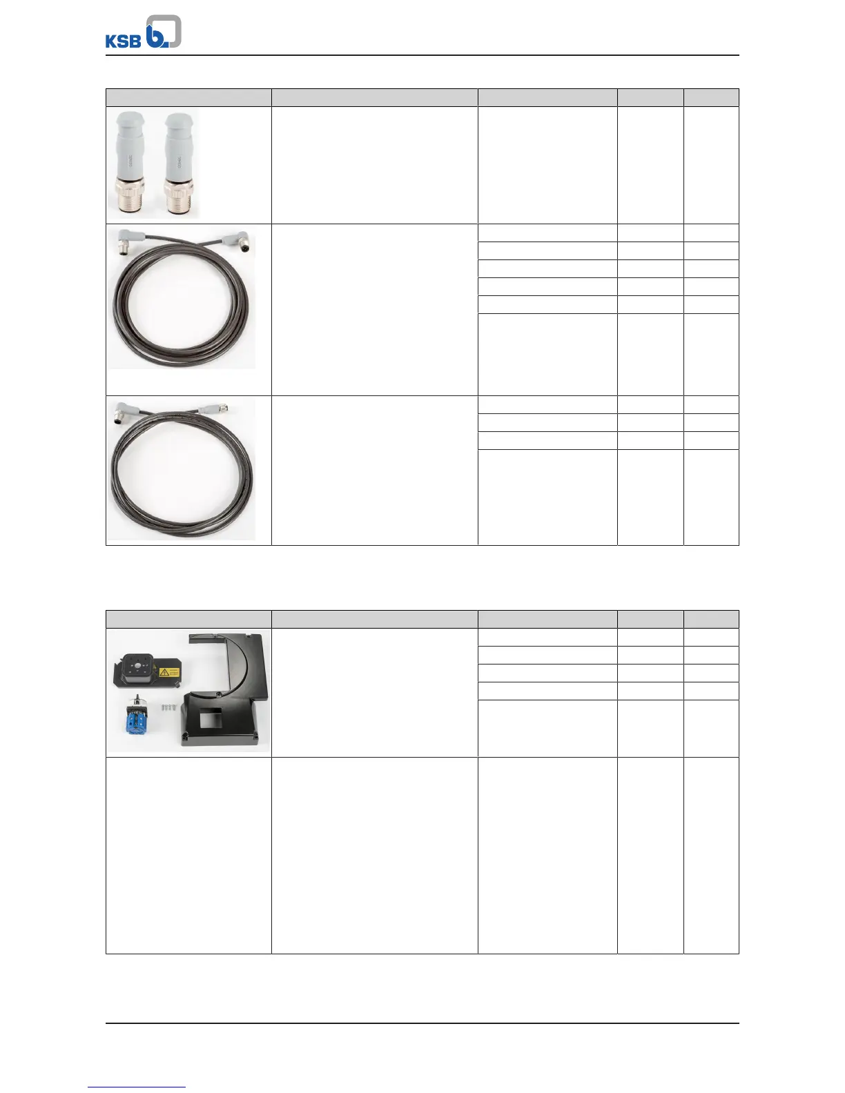
Terminating resistors
Comprising two M12 connectors,
each with integrated CAN
terminating resistor
01522993 0,3
Pre-configured bus cable for
PumpMeter crosslink
For redundantly connecting
PumpMeter via Modbus
For looping of the PumpMeter
Modbus from frequency inverter to
frequency inverter via M12 module
Can also be used for 4 to 20mA
analog sensors
Shielded
Colour: black, M12 connector:
angled, M12 connector: angled
Length 1m 01533769 0,1
Length 2m 01533770 0,2
Length 3m 01533771 0,2
Length 5m 01533772 0,3
Length 10m 01533773 0,6
Length 20m 01533774 1,2
Pre-configured PumpMeter bus
cable for connecting PumpMeter to
the M12 module via Modbus
Shielded
Colour: black, M12 socket: straight,
M12 connector: angled
Length 1m 01533775 0,2
Length 2m 01533776 0,2
Length 3m 01533777 0,3
Length 5m 01533778 0,3
12.2.6 Installation options
Table128: Optional modules for retrofitting
Description Design Mat. No. [kg]
Master switch retrofit kit
For PumpDrive 2 comprising:
Master switch, adapted C cover,
protective cover for the master
switch, wire harness
Size A 01500522 1,4
Size B 01500523 1,7
Size C 01500524 2,8
Size D 01500525 5,5
Size E 01500526 14,5
I/O extension board
For PumpDrive 2 only
Additional inputs and outputs are
made available by the I/O extension
board:
▪ 1 analog input
▪ 1 analog output
▪ 3 digital inputs
▪ 2 digital outputs
▪ 1 changeover contact relay
▪ 5 NO contact relays
Suitable for sizes A, B, C,
D and E
01496564 0,3