8 Commissioning/Shutdown
108 of 212
PumpDrive 2
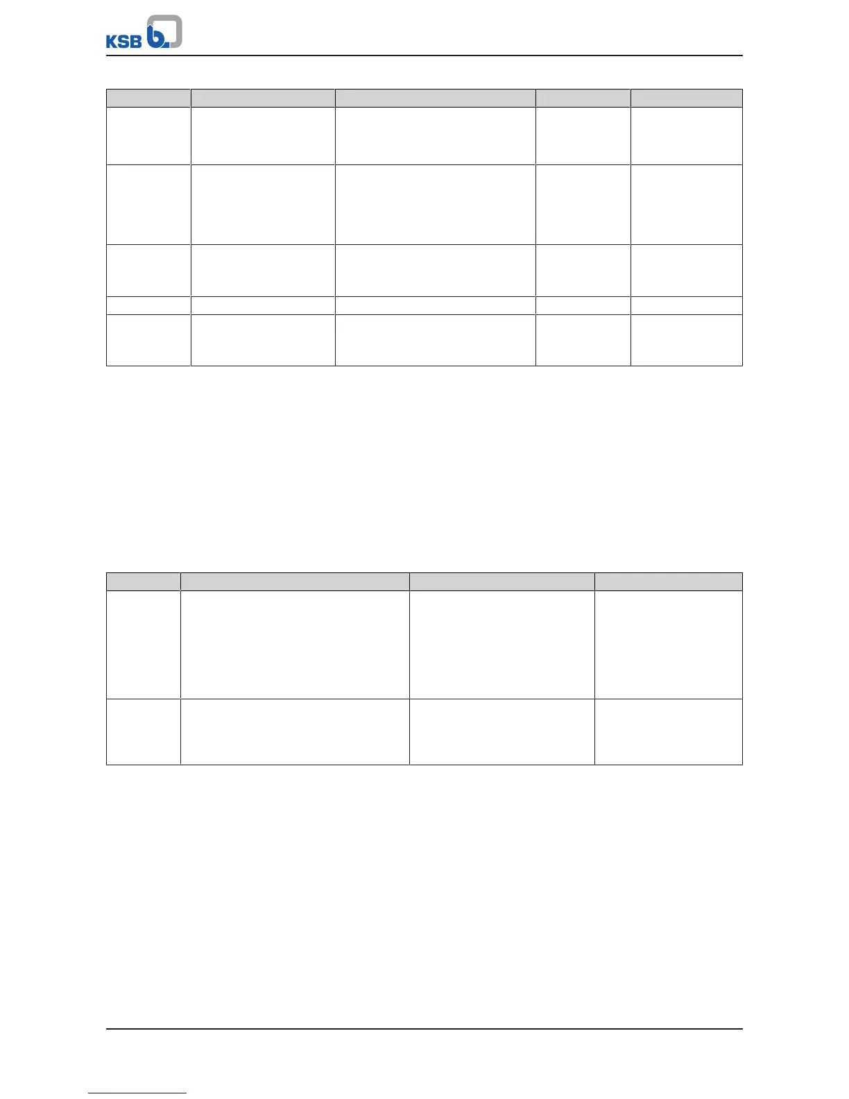
Parameter Description Possible settings Refers to Factory setting
3-9-5-1 Energy Savings Meter
Selection of method for
energy savings metering
▪ OFF
▪ Fixed Reference Power
▪ Variable Reference Power
- OFF
3-9-5-2 Fixed Reference Power
Configurable reference
power of fixed speed
pump for energy savings
meter
0 … 110 kWh - 0 kWh
3-9-5-3 CO2 Emissions per kWh
Carbon dioxide emissions
per kWh
0 … 10000 g/kWh - 500 g/kWh
3-9-5-4 Electricity Costs per kWh 0 … 1000 - 0,14
3-9-8-1 Flow Rate Estimation
Activation of flow rate
estimation
▪ ON
▪ OFF
- ON
8.8.4.4 Waste Water Function
8.8.4.4.1 Starting the pump set at maximum speed
This function ensures that a relatively high flow rate is achieved in a short period of
time. In this way, solid deposits and gas cushions are transported away at every start-
up to prevent clogging or blockage. The function is activated by the Pump Start at
Maximum Speed parameter (3-9-9-7). The duration of pump operation at maximum
speed is defined by the Duration of Maximum Speed parameter (3-9-9-8). After this
time lapses, the system switches to closed-loop control mode or open-loop control
mode with freely selectable speed.
Table76: Pump Start at Maximum Speed parameter
Parameter Description Possible settings Factory setting
3-9-9-7 Pump Start at Maximum Speed
Start-up along a ramp up to maximum
speed and maintaining maximum speed for
the duration of a defined period of time.
The function is run or executed at every
start to prevent deposits in the pump sump
and in the piping.
▪ ON
▪ OFF
OFF
3-9-9-8 Duration of Maximum Speed
Configurable period of time for which the
frequency inverter maintains maximum
speed.
0,0…600,0 180,0
8.8.4.4.2 Monitoring minimum flow velocity and pipe flushing
Monitoring minimum flow velocity
Together with the flushing function, this function makes it possible to prevent
disruptive solid deposits from accumulating in piping. When the function is activated,
the flow rate measured or estimated is used to compute the flow velocity in the
piping, the internal diameter of which is specified by parameter (3-9-9-6). Continued
operation below the minimum flow velocity (3-9-9-2) triggers a warning and,
depending on how parameter (3-9-9-1) is set, a pipe flushing routine. The duration of
operation below the minimum value is defined by parameter (3-9-9-3). The current
flow velocity of the fluid in the system can be displayed at the control panel (1-2-3-8).