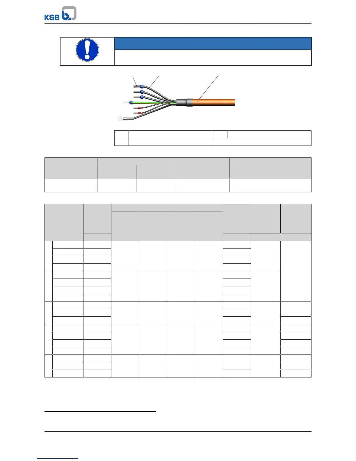
Fig.15: Structure of electric cable
1 Wire end sleeve 2 Core
3 Cable
Table27: Cable cross-section, control terminals
Control terminal Core cross-section [mm²] Cable diameter
11)
[mm]
Rigid cores Flexible cores Flexible cores with
wire end sleeves
Terminal strip A, B, C 0,2-1,5 0,2-1,0 0,25-0,75 M12: 3,5-7,0
M16: 5,0-10,0
Table28: Power/connection cable properties
Size Power Cable gland for Mains-side
input
current
12)
Maximum
core cross-
section
Cable cross-
section
KSBmotor
cable
Mains
power
cable
Sensor
cable
Motor
cable
PTC
thermistor
[kW] [A] [mm²]
A .. 000K37 .. 0,37 M20 M16 M20 M16 1,4 2,5 2,5
.. 000K55 .. 0,55 2,0
.. 000K75 .. 0,75 2,7
..001K10.. 1,1 3,7
B .. 001K50 .. 1,5 M25 M16 M25 M16 5,2 2,5
.. 002K20 .. 2,2 6,3
.. 003K00 .. 3 8,4
.. 004K00 .. 4 10,4
C ..005K500.. 5,5 M32 M16 M32 M16 14,6 16 4
..007K500.. 7,5 18,7
..011K000.. 11 25,9 6
D ..15K000.. 15 M40 M32 M20 M40 34,1 50 10
..18K500.. 18,5 43,3 16
..22K00.. 22 52,4 16
..30K00.. 30 67,7 25
E ..37K00.. 37 M63 M32 M20 M63 83,4 95 35
..45K00.. 45 99 50
..55K00.. 55 122,4 70
11) Impairment of protection provided by enclosure when cable diameters other than those specified are used.
12) Observe the information on the use of line chokes provided in the Accessories and Optional Equipment section.