7 Installation at Site
48 of 212
PumpDrive 2
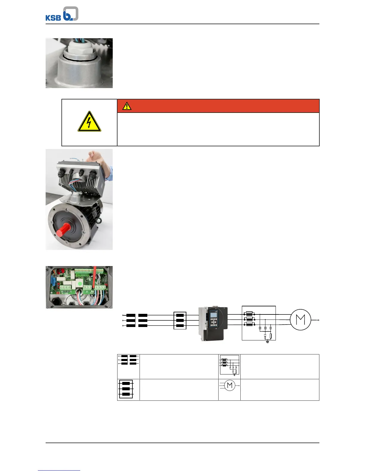
Fig.33: Inserting the O-ring
3. Place O-ring onto adapter.
DANGER
Pinching of power and motor connection cables
Risk of fatal injury due to electric shock!
▷ Never damage the insulation of the power and motor connection cables when
inserting into the opening of the frequency inverter.
Fig.34: Inserting motor
cables
4. Place the frequency inverter onto the motor adapter of the KSB SuPremE B2
motor and insert the motor cables of the KSB SuPremE B2 motor into the
opening of the frequency inverter.
5. Connect the motor cables as described. (ðSection7.4.3.3,Page40)
Fig.35: Connecting the
motor cables
6. Connect the PTC cables that are supplied as standard with the KSB SuPremE B2
motor.
7. Close the frequency inverter with the protective cover and the housing cover.
7.4.3.3.4 Installing the line choke and output filter
Output filter
(for asynchronous motors only)
Line choke Motor
(asynchronous motor)
Line choke
The line input currents may vary depending on the actual line impedance. In low-
impedance mains, higher currents may occur. To limit the line input current, external
line chokes can be used alongside the line chokes already integrated in the frequency
inverter (in the power range up to and including 55kW).
Output filter
Output filters can only be used in conjunction with an asynchronous motor.