170 General Maintenance
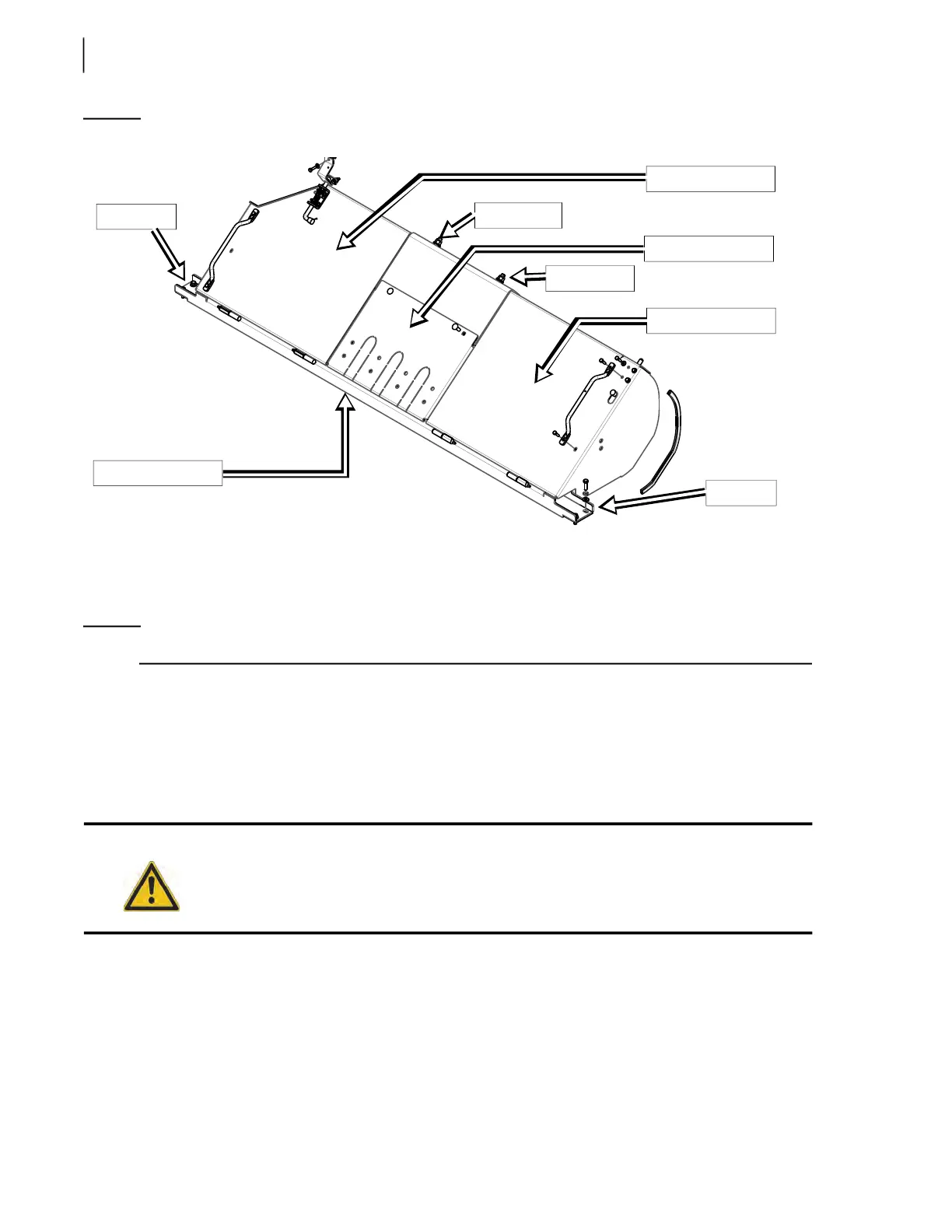
Figure 3-241
Floating panel assembly
6 bolts are to be taken out including 2 carriage bolts to remove the beam and unloose the central
cover (see Figure 3-241).
9. Remove the lower wear pad (see Figure 3-235).
NOTE: The lower wear pad is not bolted to the transversal beam.
10. Check the compression rubber inside the beam (under the scraper). Replace if needed.
11. Install a new wear pad.
12. Reinstall the transversal beam, its retaining bolts and the 2 carriage bolts (see Figure 3-241).
13. Check for even contact between the new lower wear pad and the packer/follower panels.
14. Reinstall both floating panels and close them back.
15. Reinstall both anti-spill guards.
C. Co-Mingle Units W/ Loading Arm
To replace a worn-out lower wear pad, apply the following procedure:
1. Start the engine and engage the hydraulic pump.
Warning!
Beware of the floating panel pinch points. Keep your fingers and hands away from them.
Transversal beam
Central cover
RHS floating panel
LHS floating panel
Bolts (2)
Carriage bolt
Carriage bolt
Bolts (2)