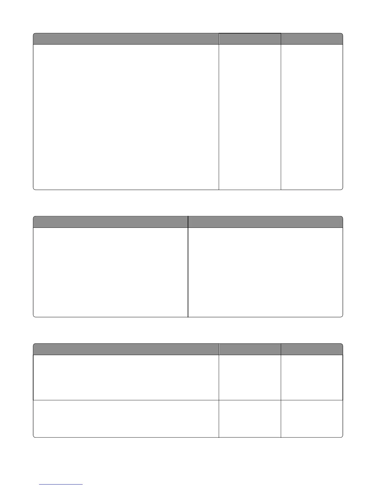
Actions Yes No
Step 11
a Turn off the printer.
b Remove the rear cover. See “Rear cover removal” on page 221.
c Disconnect the cable at JOPT1 on the controller board.
d Turn the printer on.
e Measure to voltages below:
JOPT1:
Pin 2: Ground
Pin 3: Ground
Pin 5: +24 V dc
Pin 6: Ground
Pin 7: +5 V dc
Pin 9: Ground
Pin 10: Ground
Are the voltages correct?
Contact your next level
of support.
Replace the controller
board. See “Controller
board removal” on
page 239.
Tray 2 service check
FRU Action
Tray 2 Turn the printer off.
Separate the printer from Tray 2.
Turn the printer on and check the voltages on connector J28
on the engine board.
Pins 1, 4: 3.3V
Pin 2: 24V
Pin 6: Ground
If the voltages are incorrect, then replace the engine board.
If the voltages are correct, then try using Tray 2 again. If the
printer error persists, then replace Tray 2.
Tray (x) sensor service check
Actions Yes No
Step 1
When the printer is in Ready state, pull the standard tray out. The display
should indicate Tray (x) Missing. Reinsert the tray.
Does the message remain on the display?
Go to step 2. Go to step 4.
Step 2
Check the vertical wall at the right rear of the tray for damage.
Is the tray damaged?
Replace the tray. Go to step 3.
7527
Diagnostic information
132