Operator panel removal (for CX510 models only)
Installation warning: Replace one of the following components, and perform a POR before replacing a second
component. Never replace both of the components without performing a POR after installing each one, or the
printer may be rendered inoperable:
• Operator panel assembly
• Controller board
Note: The UICC card is part of the operator panel.
Note: The following parts (FRUs) can be accessed from this section:
• 7” display
• Small interface card
• Interface cable
• UICC PCBA
• Operator panel for 7” display
• User interface support bracket
• Upper front (operator) cover
• Speaker
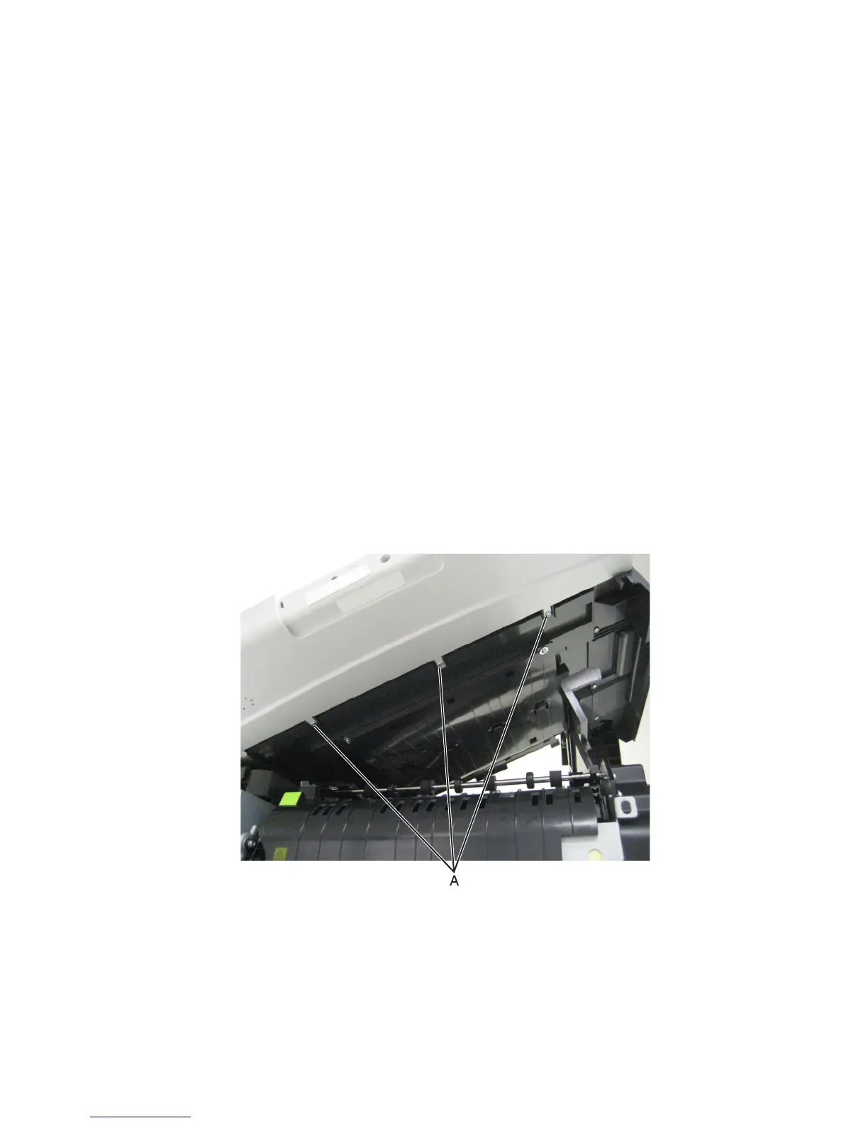
1 Open the front cover.
2 Open the scanner to give access to the bottom operator module.
3 Remove the three screws (A).
4 Carefully separate the module from that scanner and support the right end of the open door without stressing the
cables.
5 Remove the bezel.
6 Remove the screw on the right rear side of the module which secures the bracket to the upper front cover.
7527
Repair information
289