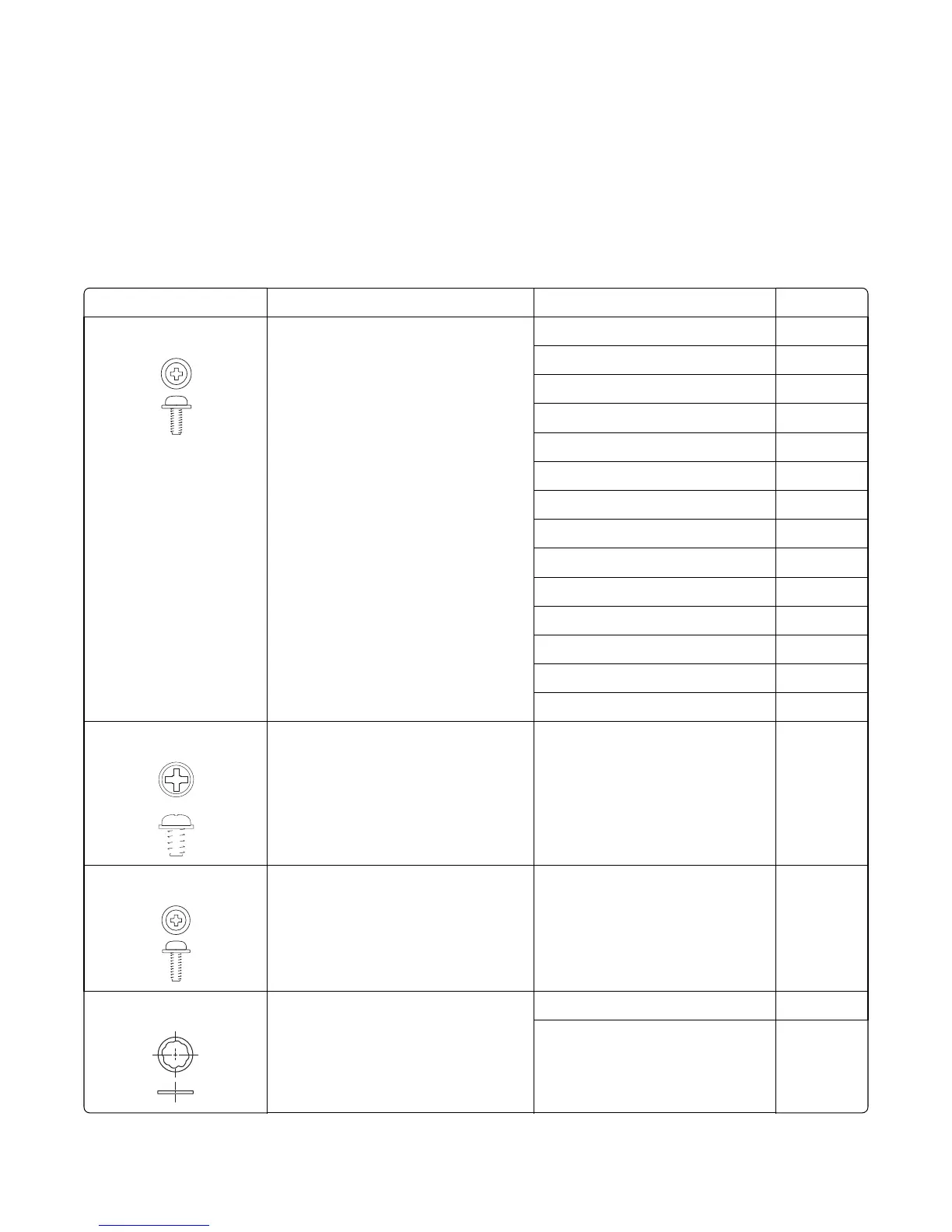
Screw and retainer identification table
The following table contains screw and fastener descriptions, locations, and quantities necessary to service the printer.
Pay careful attention to each screw type location when performing a removal. You must install the correct screw type
in each location during reassembly.
The size of the screws and fasteners are as close to their actual size as possible, as long as the printout is not scaled or
resized.
Screw and retainer identification table
P/N Screw type Location Qty
18B0832
Taptite M3 L6 panhead screw Controller board 6
EP drive 6
Fuser drive assembly 2
Fuser sensor 1
Left cover 1
Lower left frame 4
LVPS assembly 6
LVPS cage 4
Paper pick motor drive assembly 2
Rear cover 8
Toner density sensor 4
Toner meter cycle 2
Top cover 5
Wireless antenna 1
18B1236
M3x6 panhead screw Lower right frame 1
3000114
Shoulder screw Paper pick motor drive assembly 1
3000167
M3.5 internal lock washer Fuser assembly 1
Top cover 1
7527
Parts catalog
348